

The content is published under Creative Commons Attribution 4.0 International license (CC BY 4.0).
Reviewed Article:
Experimental Evaluation of Novel Levelling Methods Based on the Hohokam Stone Palette Design Evolution
Carved stone palettes are recognised as a distinctive characteristic of the Pre-Classic Hohokam culture. Palettes have been found throughout the Hohokam region, and their distribution has helped to define that region. Prior study has documented context and physical properties of palettes and examined potential uses, including as a tool for pigment processing and use (i.e., a palette). During the same Pre-Classic period associated with palette deposition, the Hohokam constructed irrigation canals by exploiting or creating contours in the landscape to direct and control the flow of water. It is supposed that the Hohokam engineered these irrigation canals without the use of levelling instruments. Based on descriptions, drawings, photographs, and measurements of Hohokam stone palettes, I constructed slate replicas and tested their suitability for use as levelling instruments. Testing led to the discovery of novel level-setting methods. These experiments demonstrated accuracy sufficient for effective and efficient use for ancient irrigation system construction and engineering. Additional study would be required to assess the likelihood that the Hohokam manufactured stone palettes for this application.
Introduction
The Hohokam Millennium
For 1,000 years (circa 450 – 1450 AD), the people known to archaeology as the Hohokam maintained a recognisable cultural identity throughout what is today southern Arizona (See Figure 1) in the United States of America (Fish and Fish, 2007b). This investigation focuses on two distinctive elements of Hohokam material culture: stone palettes and irrigation systems.
Hohokam Stone Palettes
The author’s calculations, based on White’s (2004) data, show that, at about 160 mm long by 90 mm wide by 9.5 mm thick, the average Hohokam stone palette from the Sedentary period (circa 850 –1150 AD) is about the same size as a modern (circa 2020) mobile phone. The average Pioneer (circa 300 – 700 AD) and Colonial (circa 700 – 850 AD) palettes are smaller, averaging about 128 mm in length by 73 mm width. White’s descriptions of the artifact class indicate that most palettes were made from fissile sedimentary stone, such as schist or phyllite, that was worked to expose a flat surface. Most palettes were, more or less, rectangular, although a variety of forms and irregular shapes have been assigned to the artifact class. Most, but not all, had a shallow (average 1.7 mm deep) rectangular basin carved into the flat surface, surrounded by a 13 mm (average) border. The border was often worked; what appear to be decorative sculpted elements were sometimes included, and the sides of the palette were sometimes meticulously worked. Calculations based on White’s data show that the average basin, held level and filled to the brim, could hold about 14.4 mL of liquid and that if the typical Sedentary Period Hohokam palette basin was filled half-way with liquid and then tilted (on the long axis) by as little as one (1) degree from level, some of the liquid would spill out of the basin, across the border, and over the edge.
These artifacts, and their potential uses, have long attracted the interest of the archaeologists working in this region (Haury, 1965, p. 121):
“Palettes have long been recognized as one of the distinctive traits of the Hohokam … [t]he abundance and the long life of the trait … attest to the importance of palettes, but unfortunately now, a thousand years after they were held in regard as a necessity, we can say little about their actual function.”
Further excavations and study failed to provide a satisfactory explanation (Haury, 1976, p. 288): “Palettes among the Hohokam still remain something of an enigma.”
In 2004, Devin Alan White published a monograph documenting physical characteristics, decorative motifs, and provenance of over 1,200 artifacts identified as palettes (White, 2004). White’s study identified a range of potential uses that have been proposed, including: as some part of Hohokam mortuary ritual, as part of other unspecified ritual(s), multiple (unspecified) uses, containers for pigments, trays for holding other objects (some of the larger examples), jewellery (a few of the smaller examples), holding other objects or materials for heating (a few with handles), and, the most widely accepted idea, pigment processing. White (p. 72) noted an “… absence of abundant and convincing evidence to support the notion of their use as paint palettes or pigment processing stones ” and suggested that the term “palette” be replaced with “tablet” as the descriptor for this artifact class. White also confirmed (p. 16) that palettes disappear from the archaeological record beginning with the Classic period (circa 1150 AD).
Bisulca, Santarelli, and Odegaard (2024) revisited the 1930s discovery of lead minerals on palettes with an updated, expanded, multi-analytical chemical analysis of accretions found on nearly 200 palettes from throughout the Hohokam region. This study identified what was determined to be a lead-containing pigment present on 71% of the palettes tested, with trace amounts of lead found on an additional 22%. The authors propose that the palettes were used specifically to prepare pigments (shiny black galena and white clays/caliche) for use as body paints, noting that the lead-based pigments identified have been found on no Hohokam artefacts other than these palettes.
Hohokam Irrigation System Engineering
“Making water run downhill would appear to be the easiest thing in the world.” – Charles R. Ortloff (1988)
The Hohokam built sustainable agricultural villages and communities served by irrigation canals that delivered water, often at great distances (more than 15 km), from their river sources; the larger canals were more than 18 m wide and 6 m deep (Caseldine, 2025; Fish and Fish, 2007b; Howard, n.d.). Because canals were dug directly into the desert soil and the river water was loaded with silt, the Hohokam faced significant engineering and design challenges. Where the canal gradient is too shallow, silt would accumulate, filling the canal. Too steep a gradient risked uncontrolled washout, with potential loss of the canal and other downstream, downhill, and even upstream resources. Moreover, if the canal gradient is not managed throughout its course, water would not have reached intended destinations. These hydrology considerations apply to the entire irrigation system, from main canals branching into side canals, laterals, and fields.
The Arizona Historical Society (2020) reports that more than 800 km of ancient canals have been documented in the Phoenix basin alone. Canal construction in the Salt River Valley saw significant levels of labour investment beginning no later than the Pioneer period (circa 300-700 AD) and continuing through the Classic period (circa 1150-1450 AD) (Neitzel, 1991, pp. 194-198). That is, canal construction continued long after stone palettes had fallen into disuse.
Haury (1976, pp. 142-143) noted the generally favourable topographic conditions for canal irrigation along the lower Gila, with a relatively low gradient and easily discernible terraces. He reported that the main Snaketown canal dropped at an average of approximately 1 m per km (0.0010 gradient). Haury concluded that “[w]hile the engineering capabilities of the Hohokam evoke admiration, what they accomplished was perhaps no more complicated or involved than the application of grass-roots experience in water management ,” using “trial and error and trained judgement” - without elaborating on the basis for this conclusion.
Woodson (2010) reported on over 200 km of canals with good documentation in 13 canal systems along the lower Gila, with an average gradient of 0.00145 (1.45 in 1,000) and noted that 54% of these canals had an average gradient between 0.0014 and 0.0016. He concluded that the “… overall similarity in the hydraulics of main canals suggests that the Hohokam had a shared technological knowledge for canal engineering.”
It is not known how the Hohokam identified contours in the natural topography that would be suitable for canal planning or managed canal gradients to ensure safe, efficient, and reliable operation. The gradients reported represent a consistent, but imperceptible, deviation from a reference of near-perfect level that is itself imperceptible. Howard (n.d.) notes that a simple levelling frame could have been used, although it appears that no such instrument or depiction of its use exists in the archaeological record of the region. A study by Neely and Lancaster (2015) of ancient canals in the Safford Valley notes that the “engineering involved in the planning and construction of these canals seems phenomenal considering the lack of levelling instruments and metal tools. It would appear possible that pilot extensions of the canals themselves could have served as water levels in spite of the tedious and time-consuming application involved.”
Ancient Irrigation System Engineering and Levelling Instruments
Singh and colleagues (2020) note that “[a]ll the ancient civilizations, i.e., Harappan, Egyptian, Mesopotamian, Chinese, and Minoan, that flourished and attained their pinnacle were largely dependent on the degree or extent of their advancements in water technologies .” The accomplishments of ancient civilisations in irrigation system engineering and construction, and even methods of management and governance, are better known than their associated levelling instruments and engineering methods.
Stiros (2012) reviewed levelling in antiquity from an engineering perspective – including instrumentation, error management techniques, and accuracies. Among his findings:
- Typical ancient levelling instruments employed two basic features in their designs:
- A simple method for establishing horizontal. This was achieved by observing the effect of gravity on either a suspended weight ( e.g., a plumbed line or a balanced instrument) and determining a perpendicular to that force or, directly, by observing the surface of a pool of resting water.
- A method for extending the horizontal line or, for more advanced instruments, a method for extending a fixed angle from the horizontal. Stiros notes that these instruments usually employed sighting methods ( e.g., a long tube or a pair of sights) and that other methods were possible. - Levelling or gradient-setting accuracy was not limited by the accuracy of the levelling instrument alone but rather was achieved through rigorous application of error reduction and correction procedures, including repeated, redundant, and independent measurements and techniques which would remove the effects of operator error and instrument calibration bias.
- Individuals involved in surveying were well-trained. “A basic characteristic of surveying in antiquity is that it was confined to certain groups of experts, types of guilds or even of hereditary professionals in certain towns … who followed simple, precise rules developed on the basis of the trial-and-error approach over past centuries and millennia.” (p. 49)
The levelling instruments identified by Stiros are simple, yet sophisticated and ingenious. They include the Egyptian A-frame level; the Greek or Roman chorobates ; balanced, suspended sighting tubes; and the simplest of all: a container of water from which a level line can be extended.
M.J.T. Lewis (2001, p. 251) reports that reliable information can be obtained from historic sources on levelling instruments in use from Iran to Spain from the eleventh century. Reported practice at this time included the use of what Lewis describes as a crude levelling instrument: “a bowl set on a flat base and filled with water to the brim to ensure that it was horizontal, and a plank laid across the top to sight along.”
Until the invention of the spirit level (circa 1660 AD), levelling methods using pooled water faced a common challenge of instrument calibration. When a high degree of accuracy is required, as in engineering survey applications, error on the order of 1 in 250, or even less, becomes material. At this tolerance level, accuracy is limited by the length of the pool of water used, by the width of the calibration mark, and by the operator’s ability to centre the water level within a calibration mark. For example, to achieve acceptable accuracy, the operator might be required to find the centre, within micrometres, of a 1 mm wide calibration mark - unaided, of course, by magnification. This problem is greatly compounded by the problem of calibrating instrument features used to extend a level line.
It is because of these limitations, inherent in design and materials used, that Lewis characterised ancient water-based levelling methods as crude - practical for use as construction tools, but unsuitable as engineering instruments. Lewis (2001, pp. 27-30) applies a similar critique to the plumbed A-frame level, finding it unacceptable for engineering survey applications. Lewis reported no ancient water-based levelling methods with accuracy suitable for irrigation system surveying (but notes that the historical record may be incomplete).
The average gradient of Hohokam canals reported by Woodson (2010) was 0.00145, or a drop of about 1 in 690 (or an angle of about 0.083 degrees), with control demonstrated around this average. This places the Hohokam canal levelling accuracy somewhere between that of ancient Greek aqueducts, with an average minimal gradient of about 1 in 200, and ancient Roman aqueducts, which maintained average gradients of about 1 in 1000 (Lewis, 2001, pp. 174-175).
In addition to levelling instruments, controlling gradients for irrigation system engineering requires accurate measurement of distances (both horizontal and vertical). Ancient surveying distance measurement employed materials such as ropes or cords, wooden rods, stakes, and measuring sticks - all of which could be fashioned to include measurement units (Lewis, 2001, pp. 19-22).
Experimental Task: Levelling
The focus of this investigation was to assess the potential accuracy of levelling methods in irrigation system engineering applications, using instruments constructed following the design of Hohokam stone palettes.
The basic task for this type of levelling can be described as follows. Beginning with a fixed point A, mark a second point B that is level with A. For irrigation system engineering, especially route surveying, it is convenient to locate A and B on markers set about 1.5 meters above the ground and, if necessary, remove vegetation between the points. It is also convenient to elevate the levelling instrument on a raised platform. For setting gradient, the distance between A and B would be measured using cordage. Typical distances between A and B would be between 5 and 15 meters, with a maximum of around 20 meters. Gradient could be established by introducing a measured drop (or rise) over the measured distance from A to B (that is, it might not be necessary to measure the gradient angle with levelling instruments). To extend a level plane, or a plane with an established gradient, the levelling procedure is repeated, with point B from the prior stage becoming the new point A.
Experiments replicate the basic levelling task of using the proposed levelling instruments and methods to set two level markers, A and B, separated by distances between a minimum of 5 and a maximum of 20 meters.
Palette Design and Progression
Palette features that would afford use as levelling instruments can be identified from drawings and measurements (White, 2004). Palettes begin with a flat stone surface and include a worked feature (or features), such as an incised basin, channel, or ground indentation, that, if held level, would contain water. Experiments sought insights into questions that could not be answered using existing documentation alone, including:
- Calibration and accuracy. Compared to the accuracy desired for irrigation system engineering, palettes appear to be small. Instrument size is a recognised constraint for all ancient levelling instrument designs. From drawings and measurements, it appears that the worked features might, with palettes of average length (about 150 mm) and with skilled interpolation, provide accuracy to perhaps one half of one degree (or a gradient of about 1 in 115). This degree of accuracy would still make the instrument useful, as an engineer would be better off with it than without it, but greater accuracy would be desired. The performance of smaller palettes, less than 100 mm in length, which were produced in meaningful numbers throughout the Hohokam sequence, will also be considered.
- Palette variety and evolution. The author’s analysis of non-fragmentary palette artifact data (See Table 1) suggests that palette evolution can be characterised as:
- Pre-Colonial (or Pioneer - before circa 700 AD): palette design was unstandardised1 with variable regional distribution of worked features and, compared to later periods, more irregular shapes; 55.6% of all palettes from this period had a defined border area; 13.4% had some type of side workings ( i.e. , incised groove running the length of the side or notches visible from the side); 25.5% included a ground indentation – the majority of the ground indentations, 80.1%, appear on palettes without a defined border area; and for 17.5% of the palettes from this period, the top surface was unworked. Pre-Colonial palettes are thicker than those from later periods, with deeper basins; 43.0% were less than 100 mm in length.
- Colonial (circa 700 – 850 AD): palette design generally follows a recognizable standard throughout the Hohokam region; 97.7% had a defined border - more than 50% of borders included one or more incised channels; 19.9% of palettes included a ground indentation - more than 80% of ground indentations appear within a defined border area; and 89.4% had side workings. No palettes with unworked top surfaces have been associated with this period. The Colonial period introduces elaborately carved end sculptures, appearing on 13.0% of all palettes from this period. 35.9% were less than 100 mm in length.
- Sedentary (circa 850 – 1150 AD): palette design generally follows a recognizable standard throughout the Hohokam region that is distinct from Colonial period palettes; this standard palette design was changed to include a decorated border - a wide variety of motifs have been documented, with the most common form being repeating pattern of triangles; 99.8% had a defined border; 14.7% included a ground indentation - these indentations are almost exclusively located within a defined border; and 6.0% had side workings. Again, no palettes with unworked top surfaces have been associated with this period. End sculptures appear on 3.4% of Sedentary period palettes; 27.8% are less than 100 mm in length.
- Classic (circa 1150 – 1450 AD): palettes are no longer manufactured or deposited (although canal construction continues); no successor or replacement has been identified.
Experiments included a variety of palette types to determine whether different palette designs may have impacted levelling accuracy and performance of the levelling task and whether the evolution in design represents progression toward improved functionality.
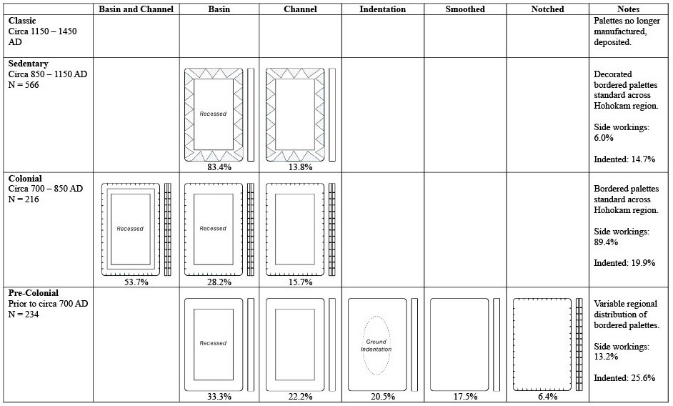
Table 1. Hohokam Stone Palettes Design: Frequency by Period. Author’s analysis of White (2004) data. Simplified representation of typical designs. Top surface and side view. Low frequency designs (less than 3%) not shown. Graphic by Michael P. Silver.
Levelling Experiments: Materials and Methods
Experiments were conducted using slate replica Hohokam stone palettes (examples are shown in Figure 2), manufactured using modern tools. These replicas do not match the elegance or craftsmanship of authentic Hohokam stone palettes, but they provide a suitable model of the essential functionality to be tested. The top surfaces of replica palettes were smoothed but not polished. Dimensions ranged from 75 x 43 mm to 220 x 150 mm. Following the Hohokam practice, most (but not all) of the replica palettes used in experiments were worked to include recessed features on the interior of the top surface, surrounded by a border area. The border area of the smallest palette was conditioned with (the author’s) skin oil; water resistant paint was applied to the border of three (3) other palettes.
Modern materials used in the experiments included tripods with a screw-adjusted levelling base, nylon cordage, a squeeze bottle for applying water, coloured levelling markers, and rolled paper hand-held sighting tubes. The Hohokam are known to have had materials that could have served in all the functions served by these modern materials2. No magnification was employed in the experiments.
I performed the experiments reported below, with the assistance of volunteers on about 20% of the tests. Volunteers included a licensed land surveyor and professional engineer, two landscape architects, and one operator with experience in irrigation system surveying field work. Experiments were performed in various locations in the State of Utah (USA), during the summer season.
Levelling accuracy for palettes and stretched cordage was assessed using a bulls-eye spirit level and mason’s line level. Both instruments can detect deviation from level of approximately 0.10 degrees (gradient of approximately 1 in 570). If readings appeared to be less than or equal to 0.10 degrees, those readings were recorded as 0.10 degrees.
The accuracy of setting level markers was assessed using a builder’s laser level.
One experiment, described below as palette instrument levelling, was initially planned. Insights gained from this experiment led to two additional experiments: water bead (optical) levelling and levelling using symmetric marker reflections.
Results
Experiment #1: Palette Instrument Levelling
This experiment assessed palette levelling accuracy and the accuracy of extending a level plane using stretched cordage.
Palette Levelling Method
As the operator introduced water onto the smoothed slate palettes, the direction and speed of water flow across the stone surface provided an immediate indication of deviation from level. As the operator adjusted the palette such that the water formed a bead on the top surface, comparing the height and shape of the bead from one end of the palette gave indication of remaining slope. Final adjustment was made by manipulating the water to form a sheet across the top surface. Differences in the height of the water sheet, from one end of the palette to the other, could be determined by observing differences in the underlying surface texture made visible by the sheeted water (relatively higher areas had a thinner sheet and showed more of the surface texture). Precision levelling was performed by observing the action of the water sheet at the outermost edges of the palette’s smoothed flat surface (See Figure 3a,b): if the palette is sloped by as little as 0.20 degrees water will recede (or evaporate) from the elevated edge or corner; if the palette is level, the water sheet recedes (or evaporates) equally from opposite edges.
Palette Levelling Results
Fourteen observations were performed with operators setting level using the method described above (See Table 2). Level was measured at the centre of the levelled palette (if the design of the palette left this area unworked and it had dried) or using the average of up to three (3) measurements along dried border areas. For 12 of the 14 observations, all spirit level readings along the long axis showed less than 0.10 degrees of slope or error (that is, approximately at the limit of the spirit level precision). The average long axis observed slope (or error) across the 14 observations was less than 0.11 degrees (approximately 1 in 520 gradient). The maximum long axis slope or error observed in a single measurement was 0.30 degrees (approximately 1 in 190 gradient).
| Test | Palette Design | Palette Length (mm) | Palette Width (mm) | Measured Slope (1) | Measured Slope (2) | Measured Slope (3) | Measured Slope (average) |
| 1 | Channel | 197 | 125 | 0.100 | 0.100 | 0.100 | |
| 2 | Channel | 197 | 125 | 0.100 | 0.100 | 0.100 | |
| 3 | Channel | 197 | 125 | 0.100 | 0.100 | 0.100 | |
| 5 | Basin | 123 | 80 | 0.125 | 0.100 | 0.100 | 0.108 |
| 6 | Basin | 75 | 43 | 0.100 | 0.100 | 0.100 | |
| 7 | Basin | 200 | 134 | 0.100 | 0.100 | 0.100 | 0.100 |
| 8 | Channel | 197 | 125 | 0.100 | 0.100 | 0.100 | |
| 9 | Basin | 75 | 43 | 0.100 | 0.100 | 0.100 | 0.100 |
| 10 | Basin | 75 | 43 | 0.100 | 0.100 | 0.100 | |
| 11 | Basin | 75 | 43 | 0.100 | 0.100 | 0.100 | |
| 12 | Channel | 197 | 125 | 0.100 | 0.100 | 0.100 | 0.100 |
| 13 | Basin and Channel | 117 | 77 | 0.100 | 0.100 | 0.100 | |
| 16 | Notched | 93 | 55 | 0.100 | 0.200 | 0.300 | 0.200 |
| 19 | Notched | 93 | 55 | 0.100 | 0.100 | ||
| Average measured slope | 0.108 | ||||||
Table 2. Palette Levelling Experiment Observations Table.
These experiments included a wide variety of palette sizes and designs. While the task required patience (but little training), every replica palette design tested could be levelled to a high degree of accuracy. The critical features required for accurate levelling are flat areas present at the edges that could be connected by a continuous thin sheet of water. While smoothing imperfections do not create a serious problem, the larger error readings observed may have resulted from defects in manufacture. These types of defects could have been detected and corrected without the use of modern methods and tools.
What is the effect on the levelling task, if any, of the various workings observed in palette design evolution? Compared to the early unworked tablet design, palettes with features such as incised basins, channels, or ground indentations would have the following advantages:
- A deeper pool of water could be contained inside the inner portion of the palette. This pool of water would accelerate the flow of sheeted water away from an elevated edge and toward opposite, lower edge. The operator could more quickly observe the effects of adjustments made to palette levelling. That is, the later designs make the levelling task more efficient.
- Workings provide additional calibration features for initial set-up and levelling. That is, by observing the action of water on worked features, an operator could detect slope and adjust without having to wait to see other effects on sheeted water. Again, later designs are more efficient.
- With worked tablet designs, operators could be trained to observe multiple indicators of slope. Also, these same multiple indicators could be observed by a second operator for training or verification. Performance using these designs would be expected to be more reliable, providing an objective basis for operator feedback.
In summary, the evolution of palette design to include features, or multiple features, worked into the top surface is consistent with a hypothesis of designers seeking improved levelling function through greater efficiency and reliability.
Extending the Level Plane Methods
This experiment involved a total of 11 observations of the level accuracy of stretched cord aligned with features of a levelled palette. Braded nylon mason line was used for cordage, with the mid-point of the cord marked for reference. After the palettes were levelled as described in the previous experiment3, the operator(s) manipulated the height of the ends of the cord so that the middle segment of the cord was aligned with features of the levelled palette. These features include the palette’s top surface, the water bead resting atop the palette, or side workings. While the cord, stretched over 10 meters or more, has a visible sag, this sag would either not be apparent in the 7 to 20 cm middle segment to be aligned with the palette or, if it were apparent, the operator would focus on aligning the endpoints of the cord segment with visible features at the ends of the palette. Because of the symmetrical set-up, it was expected that this would result in the endpoints of the visibly sagging cord being level with each other (See Figure 4).
The first four (4) tests (tests 1-4 shown in Table 3) used a 10-meter cord, which seemed to be at about the practical limit for this method. Levelling accuracy was measured using a mason’s line level placed at the centre of the cord (with no comparison of the heights or level of the cord’s end points). On the first test, the measured slope was approximately 0.125 degrees. For the next three (3) tests, measurement showed no detectable slope or error. These results suggested that: it might be possible to use a longer cord and that it a more accurate measurement result might be obtained by comparing the heights of the end points.
| Test | Palette Design | Palette Length (mm) | Palette Width (mm) | Cord Length (meters) | Measured Slope at Centre of Cord | Levelling Error (cm) - set 1 | Levelling Error (cm) - set 2 | Levelling Error (cm) - average | Levelling Error (degrees) | Levelling Error |
| 1 | Channel | 197 | 125 | 10.0 | 0.125 |
|
|
|
|
|
| 2 | Channel | 197 | 125 | 10.0 | 0.100 |
|
|
|
|
|
| 3 | Channel | 197 | 125 | 10.0 | 0.100 |
|
|
|
|
|
| 4 | Basin | 200 | 134 | 10.0 | 0.100 |
|
|
|
|
|
| 7 | Basin | 200 | 134 | 14.4 | 0.100 | -3.50 | 1.50 | -1.00 | -0.040 | 1440 |
| 8 | Channel | 197 | 125 | 14.4 | 0.100 | 3.50 | -1.00 | 1.25 | 0.050 | 1152 |
| 9 | Basin | 75 | 43 | 14.4 | 0.100 | 3.25 | 5.50 | 4.38 | 0.174 | 329 |
| 10 | Basin | 75 | 43 | 14.4 | 0.100 | 3.50 | 1.50 | 2.50 | 0.099 | 576 |
| 11 | Basin | 75 | 43 | 14.4 | 0.100 | -7.00 | -3.00 | -5.00 | -0.199 | 288 |
| 12 | Channel | 197 | 125 | 14.4 | 0.100 | 0.50 |
| 0.50 | 0.020 | 2880 |
| 13 | Basin and Channel | 117 | 77 | 14.4 | 0.100 | 2.00 | 0.50 | 1.25 | 0.050 | 1152 |
| Total: tests 7-13 |
|
| 100.80 |
|
|
| 3.88 | 0.022 | 2601 | |
Table 3. Cord Alignment Experiment Observations Table. Marker heights were measured for tests 7-13 only.
The next seven (7) tests (tests 7-13 shown in Table 3) used a 14.4-meter cord (limited somewhat by the space I had available to work with). For these tests, the primary measure of levelling accuracy was obtained using a builder’s self-levelling laser level, to measure the difference in the height (in cm) of the ends of the cord. For six (6) of the seven (7) tests, the cord set-up (but not palette levelling) was repeated, reversing the ends of the cord, with the operator(s) “blinded” to the results of the first set-up. For these tests, the mid-point (or average) of the two resulting measurements is used as the measure of levelling accuracy. In the other test (test 12) only one cord set-up was performed (again, with the operators “blinded” to the result).
Extending the Level Plane, Results of 14.4-meter cord experiment
Laser level measurement of end point placement showed error ranging from 1 in 288 (a 5 cm error in 14.4 meters) to 1 in 2880 (a 0.5 cm error in 14.4 meters). In repeated tests, errors and tend to cancel each other out. Across the seven (7) tests, 100.8 meters was spanned, with a total (summed) error of 3.88 cm, for an overall error of approximately 1 in 2600.
While the operators were able to accurately align cordage with levelled palettes without side workings, when these features were available, operators used them for calibration. These workings gave the impression that, if palettes were used as levelling instruments, the design intent was to guide the eye in aligning cordage. This suggests that the (useful) practice of extending the level plane using cordage may have been abandoned (or curtailed) in the Sedentary period, when side workings become rarer.
Larger errors were observed in tests involving the smallest (75 mm length) palette, a limitation in instrumentation that could have been known to the Hohokam. Nevertheless, even these smaller palettes could serve as effective instruments for this application, in that they would represent an improvement over unaided reckoning.
In practice, even using a modern tripod as the instrument stand, it was easier to allow adjustment to the height of either or both ends of the cord so that the middle segment was aligned with the levelled palette at a fixed height. Otherwise, it was necessary to reposition (and, possibly, re-level) the palette while seeking to level the cord. This can be easily accommodated in the levelling task as the measured vertical distance from the final position of the cord end, above or below the fixed point A, can be translated from the final position of the opposite cord end to set B.
Palette Instrument Levelling Conclusions
The smoothed stone palette instrument design, using sheeted water, overcomes a significant water-based instrument calibration problem. Sheeted water can make micrometre-level differences in the elevation from one end of a palette to the other unambiguously visible. This levelling method was not reported in any of the historical or archaeological sources identified for this study.
The line or plane of the levelled palette can be accurately extended with cordage. Small, smoothed palettes made from fissile stone, combined with cordage, and used in this manner, would provide sufficient accuracy for use in ancient irrigation system surveying, engineering, and construction activities. Smaller palettes may have been used for tasks requiring a lower level of accuracy – field layout, for example – with larger palettes intended for tasks requiring greater accuracy such as extended canal route surveying. The design changes observed in palette evolution may point to changes in engineering practices.
Experiment #2: Water Bead (Optical) Levelling
The water bead levelling method described in this section has no direct analogue in engineering history sources. I had not imagined this method prior to experience with the palette instrument levelling experiment described above.
I would expect that, once the Hohokam engineer had learned to level their palette and had it elevated on a platform, they would immediately try to project level by sighting across the top of the instrument. They might close one eye and squint. They may have a colleague stand in the distance holding a target. They might even provision themselves with a small hollow sighting tube (for example, Haury, 1976, p. 304). These sighting methods would be useful for getting a general sense of level. It would be better than unaided reckoning, but not sufficiently accurate or reliable for canal engineering.
What would be missing would be a way to fix the operator’s view such that it is steady and perfectly (or nearly so) aligned with the level water surface. Ancient engineering methods used metal sighting tubes or aligned sights (similar to gunsights) for this purpose (for example, Lewis, 2001, pp. 36-50). Instruments using this design had to be calibrated to ensure that the sight line was aligned with level.
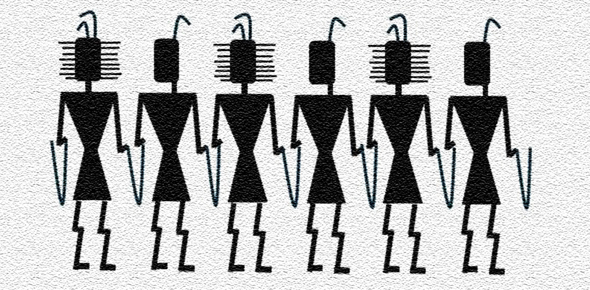
A well-known Hohokam artifact (for example, see Fish and Fish 2007a, p. 40) inspired the instrument design used in this experiment. This large vessel from the Sedentary period depicts a group of human figures (See Figure 5). It appears that these figures are connected, not hand on shoulder, as Haury (1976, p. 237) described Hohokam dancers, but by holding something (which could be cordage). The legs of the figures are unlike anatomically concordant Hohokam representations of dancers, hunters, or burden bearers – as if the activity is depicted as observed from a distance, with the view distorted by heat waves. The face of every second figure is partially obscured by what could be interpreted as a stack of palettes – as if a person was peering through such a stack.
Review of this artifact led me to a question of potential palette use: could, or how could, a stack of Sedentary period palettes be used for levelling?
Water Bead Levelling Methods
This experiment again used smoothed, but not polished, slate palettes. All palettes used included a shallow rectangular basin recessed into the top surface – a typical feature for Sedentary period palettes. The basin filled most of the top surface and was surrounded by a border area. This basin would contain and maintain for a time (even in a hot arid environment) the water bead that was used for setting markers to level. Experiments assessed the accuracy of setting markers to level.
This experiment tested the levelling accuracy obtained by sighting along the surface of a water bead resting upon a slate palette, with the operator’s view framed using another palette stacked above. The palettes used ranged from 120 to 200 mm in length. The operator introduced water into the basin of a palette, levelling much as described in the prior experiments (although the highest level of accuracy was not required as the water bead is self-levelling). With the palette levelled, the operator added water to ensure a bead was formed, visible above the level of the palette border. The operator then placed spacers – four small, matched, slate blocks (about 7 to 10 mm in height) around the palette border. Another palette was placed atop the spacers, a water bead was formed on this stacked palette, and another palette was similarly placed. The gap between the water bead surface and the bottom of the palette stacked above then became a level sighting device (See Figure 6). Looking through the gap, the operator can determine the position of level markers, relative to the level plane formed by the water bead.
Through these experiments, I learned that it can be difficult, peering through this dark gap, to determine exactly where the surface of the water lies. To aid in calibration, the operator can use reflections on the water surface. For example, if the reflection of the top portion of the marker is visible to the operator, then both the operator’s eye and the top of the marker are above the plane of the water surface. If the operator then lowers their position to the point where the reflection disappears, the lowest point visible on the marker is (almost exactly) in the plane of the water surface.
Water Bead (Optical) Levelling Results
Thirteen tests were performed, with readings taken from eight (8) different palette set-ups (See Table 4); distances between backsights and foresights ranged from 12 to 20 meters. The maximum error observed was 0.138 degrees (about 1 in 400). Six (6) of the 13 observations had error gradient less than 1 in 3,000 (which is close to the limit of reliable testing with the laser level instrument used). Across the 13 tests, 201.5 meters was spanned, with a total (summed) error of 9.06 cm, for an overall error of approximately 1 in 2,200.
| Test | Palette Design | Distance Between Markers | Levelling Error (cm) | Levelling Error | Levelling Error |
| 14(a) | Stacked | 15.8 | 0.50 | 0.018 | 3160 |
| 14(b) | Stacked | 15.8 | 0.50 | 0.018 | 3160 |
| 14(c) | Stacked | 17.4 | 0.50 | 0.016 | 3480 |
| 14(d) | Stacked | 17.4 | -0.25 | -0.008 | 6960 |
| 101 | Stacked | 20.0 | 5.00 | 0.143 | 400 |
| 102(a) | Stacked | 16.0 | 3.35 | 0.120 | 478 |
| 102(b) | Stacked | 16.0 | -2.74 | -0.098 | 584 |
| 104 | Stacked | 14.5 | 3.50 | 0.138 | 414 |
| 105 (a) | Stacked | 12.0 | 0.25 | 0.012 | 4800 |
| 105 (b) | Stacked | 13.4 | -1.30 | -0.056 | 1031 |
| 106 | Stacked | 14.4 | 1.00 | 0.040 | 1440 |
| 107 | Stacked | 14.4 | 0.25 | 0.010 | 5760 |
| 108 | Stacked | 14.4 | -1.50 | -0.060 | 960 |
| Total | 201.5 | 9.06 | 0.026 | 2224 | |
Table 4. Water Bead (Optical) Levelling Experiment Observations Table. Beginning with Test 101, a revised data collection form was instituted. Tests 14, 102, and 105 involved the levelling of multiple markers from a single palette stack set-up. Test 103 employed a levelling method that is not included in this study.
During this experiment, I determined that the larger errors observed (in tests 101, 102, and 104) resulted from an inadvertent error in technique, where I was sometimes sighting based on the reflected image, rather than the actual target. Once one is aware of this error, it is easy to avoid and would a simple matter to address in training.
Water Bead (Optical) Levelling Conclusions
This experiment shows that stacked slate palettes can be used to accurately extend the level plane of the surface of beaded resting water. Stacking palettes creates a sighting gap and presents visual cues, including reflected images, that can be used by trained operators for setting markers to level with sufficient accuracy for use in ancient irrigation and hydrologic system surveying, engineering, and construction activities.
Compared to levelling using cordage, water bead levelling is a breakthrough innovation in accuracy and efficiency. Because sighting uses the beaded water surface directly, the instrument is partially self-levelling and requires no calibration. Repeated, incremental, marker adjustments are generally not required. If desired, an operator or crew can set a short line, or curving line, of markers from a single instrument setup. Longer distance sighting might be possible. If this method was discovered and adopted, instrument makers would no longer have a reason to work grooves or notches into the sides of the palettes - which is a palette design change observed beginning with the Sedentary period.
If palettes were used for optical level setting, this practice might also influence the design of sighting markers. Peering through the narrow gap, the operator’s task would be facilitated by markers that stand out from the background – for example, markers with bold geometric patterns and painted with contrasting hues. Design might also include vertical asymmetry, to indicate to the operator whether they were looking at the top portion of a marker or its reflection. This is consistent with what is seen in the decorative motifs of the Sedentary period palettes (See Table 1). The most common decorative motifs are running patterns of triangles, lightly incised into the border. If painted in contrasting hues, these motifs would present a sawtooth pattern that could aid in calibrating marker set up and would be reversed in the vertical dimension in the reflected view. It is possible that the Sedentary period palettes themselves also served as level markers.
Experiment #3: Levelling Using Symmetric Marker Reflections
Again, I had not imagined the symmetric marker reflection method that was tested in this experiment prior to my experience with the palette instrument and water bead levelling experiments described above. The symmetric marker reflection levelling method described in this section has no analogue in historical engineering sources.
This experiment tested a levelling system that could have been developed based on long experience with water levelling using symmetric set-ups. Operators may have discovered that when markers were levelled using cordage and a centred palette containing water, if the operator positioned their eye at the vertical mid-point of one marker, the reflection of the other could always be seen in the centred water surface (See Figures 7 and 8). With this levelling system, the water surface functions as a self-levelling mirror and a flat, smoothed stone surface is no longer required. Accuracy depends on symmetric horizontal positioning of markers and the water container - using stretched cordage, this is a straightforward, even elementary, measurement task.
Levelling using Symmetric Marker Reflections Methods
This experiment involved three (3) observations using a levelling system consisting of a shallow water container placed midway between and below two levelling markers. The operator adjusted the level of the markers such that, when they positioned their eye at the vertical mid-point of one marker, the reflection of the other marker could be seen, centred, on the water surface mid-way between them. Markers were painted 150 mm square canvas boards. The water containers were shallow basins, also about 150 mm long. Three set-ups were used, with markers separated by an average of 8.4 meters.
Levelling using Symmetric Marker Reflections Results
Three (3) tests were performed (See Table 5); distances between markers ranged from 4.7 to 14.4 meters. The maximum error observed was 0.094 degrees (about 1 in 600). Across the three (3) tests, 25.2 meters was spanned, with a total (summed) error of -0.25 cm, for an overall error of approximately 1 in 10,000.
| Test | Palette Design | Distance Between Markers | Levelling Error (cm) | Levelling Error | Levelling Error |
| 109 | Container | 14.4 | -1.50 | -0.060 | 960 |
| 110 | Container | 4.7 | 0.25 | 0.030 | 1880 |
| 111 | Container | 6.1 | 1.00 | 0.094 | 610 |
| Total | 25.2 | -0.25 | -0.006 | 10080 | |
Table 5. Symmetric Reflections Levelling Experiment Observations Table
Levelling using Symmetric Marker Reflections Conclusions
Symmetric marker reflections can be used to accurately position level markers, with sufficient accuracy for use in ancient irrigation and hydrologic system surveying, engineering, and construction activities.
Levelling using symmetric marker reflections is another breakthrough innovation in efficiency, with no loss of accuracy. Any shallow water container placed on the ground can serve as the levelling instrument, training is simple, and results can be easily verified by a second operator. Repeated, incremental, marker adjustments and vertical offset measurements would generally not be required.
As with other optical methods, levelling marker design would be important when using symmetric marker reflections. Designers would seek high contrast with the background behind and above the markers and surrounding the centred water container (if working at night, small flames might serve as excellent markers - although this approach was not tested).
If this method had been discovered by the Hohokam, there would no longer be a need to manufacture palettes for irrigation system engineering purposes. Indeed, as a water container, the palette form is a poor tool for this application: a palette doesn’t contain much water if not set to level, whereas a shallow bowl is relatively robust in this sense. Moreover, fissile stone is not a particularly good source material for this type of water container.
If and when the symmetric marker reflection levelling method was instituted, the Hohokam would likely have abandoned the manufacture of stone palettes for levelling purposes. If, at this time, the palettes served no other purposes, or if palette replacements were developed for alternate purposes, palettes would disappear from the archeologic record - as has been documented at the beginning of the Hohokam Classic period. It is not clear that the symmetric marker reflection levelling method, which would have replaced or supplanted palette-based levelling methods, would (or could) be identified from the Classic period archeologic record or artifact assemblage - especially as this method has not previously been reported and no one would have known to look for it.
Limitations
The experimental results data should not be considered an upper bound for the accuracy that might be obtained from the methods presented. Operators had little opportunity for practice or skill development. Most tests were performed by a single operator (the author), without the type of error detection and correction that would be available if working as part of a crew. Measurements of levelling accuracy often approached or exceeded the accuracy limits of the modern instruments used. Greater accuracy over longer distances might be achieved for the optical methods (water bead levelling and symmetric marker reflections) using approaches that were not tested - for example, extending the distances, testing larger markers, or using small flames as markers and working at night.
Testing did not include palettes with decorative sculpted elements. From descriptions, measurements, and photographs, it does not appear that these elements would interfere with levelling methods described, nor do they appear to offer functional advantages.
Discussion
This review of instruments and methods that could have been used in ancient irrigation system engineering has identified novel approaches to overcoming accuracy and calibration challenges inherent in water levelling instrumentation:
- Small deviations from level, on the order of 1 in 500, can be reliably detected using sheeting action of water on smoothed flat stone.
- A level line or plane can be accurately extended by aligning cordage with a levelled flat stone tablet.
- A level line or plane can be accurately extended by sighting along a (self-levelling) beaded water surface, raised slightly above the rim of a container.
- Level can be accurately determined using symmetry and light reflection on a (self-levelling) water surface.
Across 23 observations using the three levelling methods tested and measuring maker placement, a total distance of 327.5 meters was spanned with a total (summed) error of 12.7 centimetres, resulting in a total error of about 1 in 2,500 (See Table 6). The accuracy of these levelling methods rivals that of previously reported ancient engineering methods (Lewis, 2001, pp. 167-180).
| Levelling Method | Tests | Distance Spanned | Levelling Error | Levelling Error | Levelling Error |
| Cord Alignment | 7 | 100.8 | 3.88 | 0.022 | 2601 |
| Water Bead (Optical) | 13 | 201.5 | 9.06 | 0.026 | 2224 |
| Symmetric Reflections | 3 | 25.2 | -0.25 | -0.006 | 10080 |
| Total | 23 | 327.5 | 12.69 | 0.022 | 2582 |
Table 6. Levelling Experiments Summary Table.
The smoothed stone levelling method could have been developed through experience with a basic irrigation system construction method: placing a stone trough in the bottom of a ditch under construction to verify that water will flow in the desired direction.
The progression in materials and methods outlined in this study appears to be consistent with the Hohokam archaeological record (including canal construction) and recognised palette evolution sequence (Haury, 1965, p. 124), including the disappearance of the palette in the Classic period. Unless some inconsistency can be demonstrated, it appears at least plausible that the Hohokam manufactured at least some stone palettes for use as levelling instruments in irrigation system engineering. None of the levelling methods demonstrated in this study have previously been reported, and they have not been considered in past studies of potential palette use. Additional study would be required to support assessment of the likelihood of this use.
These levelling methods have not previously been reported in historic engineering or archaeological literature. These are practical methods that use materials, technology, and knowledge available to ancient peoples. It is possible that other ancient cultures identified and exploited these levelling properties of water and stone, but that their instruments have not been recognised in the archaeological record. Indeed, if not for depositional practices, distinctive design, dedication to craftsmanship, and meticulous curation, the levelling potential of the Hohokam stone palette that was demonstrated in this study, and its possible successor method, might not have been recognised. With these novel levelling methods identified, it may be worthwhile to review archaeological and historic sources for other ancient irrigation societies for potential applications.
Acknowledgement
The author would like to thank an early (anonymous) reviewer who suggested the application of experimental archaeology. My thanks also to the volunteers that helped with experiments, with special thanks to my father, Duncan J. Silver, Licensed Land Surveyor and Professional Engineer, for his assistance with experiments and insights into engineering practice. The author is responsible for any shortcomings in the design or execution of this study.
Funding Statement
The author received no external funding for this study.
Data Availability Statement
Hohokam stone palette data used in this study were obtained from White (2004).
Competing Interests Statement
The author has no competing interests to declare.
- 1
Out of more than 200 non-fragmentary palette artifacts from this period, six (6) take the form of an open trough. These are described by White (2004) as “proto-palettes.” This design may have afforded use in construction applications (e.g., checking that a ditch is sloped in the right direction), but not in the manner evaluated in this study. The proto-palette design was not included in the experiments that follow.
- 2
I confirmed experimentally that the function of the modern screw adjustment could be served by using small wooden wedges, which were known to be produced by the Hohokam.
- 3
Most tests from the previous experiment were also included in this experiment.
Country
- USA
Bibliography
Arizona Historical Society, 2020. The Hohokam and the Rise of Phoenix. Available at: < https://arizonahistoricalsociety.org/wp-content/uploads/2021/03/CAE20-034-Activity_Hohokam-Canals_rev.pdf > [Accessed: 6 August 2026]
Bisulca, C., Santarelli, B., and Odegaard, N., 2024. A Multi-analytical Characterization of Minerals on Hohokam Palettes. KIVA, 90(4), pp.493–514.
Caseldine, C.R., 2025. A Reevaluation of Hohokam Irrigation Systems in the Lower Salt River Valley, Arizona. KIVA, 91(2), pp.180-203.
Fish, P.R. and Fish S.K., 2007a. Community, territory, and polity. In S.K. Fish and P.R. Fish (Eds.), The Hohokam Millennium . School for Advanced Research Press. pp. 39-47.
Fish, S.K. and Fish P.R., 2007b. The Hohokam millennium. In S.K. Fish and P.R. Fish (Eds.), The Hohokam Millennium, School for Advanced Research Press. pp. 1-11.
Haury, E.W., 1965. Stone palettes and ornaments. In H.S. Gladwin, ed. Excavations at Snaketown: Material Culture, University of Arizona Press. pp. 121-134.
Haury, E.W., 1976. The Hohokam: Desert Farmers and Craftsmen. University of Arizona Press.
Howard, J.B., n.d. Hohokam legacy: desert canals. Water History. Available at: < http://www.waterhistory.org/histories/hohokam2/hohokam2.pdf > [Accessed: 6 August 2026]
Lewis, M.J.T., 2001. Surveying Instruments of Greece and Rome. Cambridge University Press.
Neely, J.A. and Lancaster, D., 2015. The prehistoric bajada ‘hanging’ canals of the Safford basin: Small corporate group engineering in southeastern Arizona. Archaeology Southwest. Available at: < https://www.archaeologysouthwest.org/2015/10/06/ancient-engineering-hanging-canals/ > [Accessed: 6 August 2026]
Neitzel, J., 1991. Hohokam material culture and behavior: The dimensions of organizational change. In G.J. Gumerman, ed. Exploring the Hohokam: Prehistoric Desert Peoples of the American Southwest. University of New Mexico Press. pp. 177-230.
Ortloff, C.R., 1988. Canal builders of pre-Inca Peru. Scientific American, 259(6), pp.100-107.
Singh, P.K., Dey, P., Jaina, S.K., and Mujumdar, P.P., 2020. Hydrology and water resources management in ancient India. Hydrology and Earth System Sciences , 24, pp.4691–4707.
Stiros, S.C., 2012. Levelling in antiquity: Instrumentation, techniques, and accuracy. Survey Review , 44(324), pp.45–52.
White, D.A., 2004. Hohokam Palettes. Arizona State Museum.
Woodson, M.K., 2010. Re-drawing the map of the Hohokam canals in the middle Gila River valley. Journal of Arizona Archaeology , 1(1), pp.5-20.