
The content is published under Creative Commons Attribution 4.0 International license (CC BY 4.0).
Reviewed Article:
Basics of Theoretical Foundations in Historic Experimental Studies in the Sense of Practicability
Researchers working in historical disciplines (history, archaeology, art history, legal history, theology) can draw on a source base that has grown in varying degrees. Nevertheless, source material especially for older periods remains incomplete, difficult to access or fragmentary. New insights into performance in a historical context of use - additionally to the fruitfully and carefully conducted ethnological comparison - are to be gained by supplementing, reconstructing and experimentally testing only fragmentarily preserved material or/and described evidence under historical conditions. Beyond the individual object, such reconstructions have epistemological relevance if they are methodologically controlled and verifiable. This approach is based on an ever-increasing number of theoretical considerations in experimental archaeology (e.g. Coles, 1979, pp.36-39; Reynolds, 1994; Mathieu, 2002, pp.1-8), which are sometimes oriented towards concrete reconstruction, sometimes providing a sectoral or national inventory, rarely undertaking historically overarching classifications. This approach goes beyond this, also in technical terms, by conceptually including written sources and opening the discussion of methods and theory to history and, in principle, to the historical sciences–but not without starting from concrete examples that are no longer purely ‘archaeological’ in nature. With its new focus on practicability, the approach can be understood as a ‘practicability turn’: the targeted empirical reproduction of artefacts as well as their proven effectiveness and contexts of action allow central and additional questions about pre-modern societies to be answered in addition to textual and material traditions.
Introduction and Development
B. Tang (2026) categorized, by systemising the terminology in the issue of EXARC Journal 2026/1, experimental archaeology (in China) broadly into five tiers of research: 1) with focus on the reconstruction of ancient artefacts, 2) with focus on the reconstruction of ancient technologies, 3) with focus on the reconfiguration of archaeological features, 4) with focus on the reconfiguration of ancient human behaviours, and last 5) with focus on the reconfiguration of social systems. This approach should now be opened not only to a broader source base from other historically oriented disciplines, but also to the repertoire of theories developed in the historical disciplines, expanding them to include practicable, historically contextualized theory, in addition to the efforts of ethnology, which can be utilised through careful comparison. In doing so, these considerations contribute to a methodologically consistent, verifiable foundation for the experimental reconstruction of craft skills in pre-modern and early modern societies. A large part of the material and written tradition of Greek and Roman Antiquity for example–varying from region to region, but overall, up to 90-95%–has been lost. What has been preserved is of varying quality or significance, as the selection was usually made at random. Furthermore, what has been handed down to us is often fragmentary. Furthermore, the production circumstances and the necessities of everyday life were not recorded in writing, and the products themselves were partly made of perishable materials, which were only preserved under favourable climatic conditions and then possibly not representative of individual regions. The rare texts were often written by people (who were not dependent on daily earnings) without the relevant specialist knowledge. So, with no information about the essential basics of craftsmanship our knowledge of the reality of life for the general population, around let us say 90%, is considerably limited. Most craftspeople do not describe their production processes: because of the time-consuming nature of their work, the lack of their writing abilities and because of tactical considerations not to reveal successful techniques. Analogies (from other regions, other times, other cultures at a similar technical level) are only of further value to our cause if we can incorporate the traditions encountered there into the reconstruction or reconfiguration process.
Subjects that deal with history have divided their areas of responsibility according to the objects they focus on. We pursue an equal, interdisciplinary approach, since in principle the processes of understanding are the same for the respective objects of the past for which they declare their primary responsibility.
Combining textual reconstruction or interpretation with the creation of a handmade product yields significant additional insights: the intellectual interpretation based on sources and artefacts can be supplemented by testing the actual products, while conversely, the end product must constantly be measured against the texts and artefacts. This results in additional and mutual support, which can ultimately raise the level of insight to a significantly higher level. By testing the product for its performance potential, the criterion of functionality is added to the criterion of plausibility (as in pure conventional interpretation). To make this possible, it is usually, if not always, necessary to supplement the textual or material basis when replicating. Other additions on a 1:1 scale, in simulations or models, can show scaled alternatives or offer improvements, thereby recreating or replacing the experience of generations of craftsmanship. Full functionality, especially of tangible products, is necessary because only then is performance in accordance with the intended purpose possible. If all additions have been substituted on the basis of parallel finds as close as possible in time, and then the performance has been tested in the original context of the intended use, we have gained something in terms of our knowledge. This is all the more true as each step of the reconstructive and supplementary production is carried out according to contemporary manufacturing criteria and is documented accordingly. Nevertheless, the result of a reconstruction and its testing are not worth much on their own if they are not placed in a higher-level frame of reference, for example in a higher-level historical context (Huinzinga, 1942, p.104; Faber, 1982, pp.24-26). That means more than just reconfiguration of human behaviours and social systems. Experimental archaeology already depicts ancient and pre-modern contexts (for example Guédelon (Comité Régional du Tourisme de Bourgogne-Franche-Comté, 2023; Coates, et al, 1995; de Weerd, 2001; compare Petersson and Narmo, 2011). Experience and findings from parallel discoveries and findings are incorporated to obtain a 1:1 full picture (Dreyer, et al., 2022a, pp.566-581). Furthermore, by reconstructively comparing the same product category from different periods and by conducting performance tests in a historical context, developments over longer periods can be explored.
The canon of methodological procedures in historical studies has long been expanded by the analytical procedures of the social sciences, which are also empirical and relate to the present. Thus, the cooperating natural sciences can be methodically and carefully integrated under a historical question. This also applies to the question of the personnel employed, which is part of the empirical approach, as performance tests are personnel-intensive. The concept of citizen science is of value here and recently gained scientific recognition (Dreyer, 2022).
Cultural theories under the umbrella of praxeology have already included physical actions and their technical instruments in the production of knowledge and truth, thereby expanding the spectrum of knowledge. “ Practical theories assume that ‘the social’ is located in the interactions of competent actors themselves and not in an upstream structural, normative or linguistic-communicative realm outside the actors ” ... “ Action and structure thus form a dialectical unity, in the sense that structural elements as properties of the actors enable and produce their actions, while these actions, as a result, as a consequence of action, stabilize or modify the same structural elements .” (Welskopp, 2014, p.110) The stability of the social order is characterised by a high proportion of routine activities that would be inconceivable without recourse to knowledge bases; changes in this order of human actors are less creative than gradual). Regarding our concern, the documented artefact as a ‘result’ is then the starting point for drawing conclusions about the knowledge bases, interactions, and consequences in application (especially through the tests) that are no longer documented but can now be carefully explored with the new theory. The “material turn”, to name one offshoot in this context, aims to explore the increased interest in materials and materiality (Schubert, 2010, p.1). Criticism has not been lacking (Keupp, 2017). However, if the concept of the ‘material’ refers to ‘the inescapable physicality of the actor and his interaction with things, with artefacts’, without artefacts themselves necessarily having to acquire actor qualities as ‘actants’ (Welskopp, 2014, p.111), we can nevertheless conclude for our purposes in the ‘practicability turn’ that the reconstructed ancient ship places the object itself at the centre and gives it an intrinsic value, which, although created by humans, also serves as a point of reference for humans. The materials of the ship have an intrinsic value and also influence human actions and perceptions, which can now be explored through construction and testing.
The reconstructive theory with the new focus in the ‘practicability turn’ now aims to build on this and systematise existing (including pre-scientific) initiatives and integrate them into scientific practice. The methodically structured, scientifically sound reconstruction of everyday production processes and their realistic testing in the context of overarching historical questions is intended to counter the above-mentioned criticism of conceptual armament and microcosmic fragmentation, while at the same time compensating for the paucity of sources, especially for the non-elite strata of pre-modern societies. Thus, the replica as an object of knowledge is simultaneously under pressure to prove itself, which leads the researcher who produced it back to the validity of his hypotheses and additions, and is available to the scientific community for examination in its entirety and at the same time dissected through the description of its creation and testing, and is thus objectified (Fabian, 1983; Assmann, 2006; Daston and Galison, 2007).
In the ‘practicability turn,’ the focus of investigation is therefore on the material products; but they are produced to close the gaps in knowledge under overarching questions with the participation of scientific disciplines in practical performance tests under historically realistic conditions. In the process, the prerequisites and conditions of the product of human endeavour are also explored. The reality check is intended to highlight the goals, successes and failures, as well as the limitations of those who acted in the past. Their performance and the product's proven track record are to be evaluated in comparison with other later/earlier or competing contemporary products to lend depth to the assessment. Communities that still use traditional craft methods today (such as in traditional boatbuilding) can be helpful when historical records are lacking, provided that the historical context is taken into account and reliable information is available in written form, for example through ethnologic studies.
However, the reproduction of historical handcrafted products has been practiced for a long time in different enterprises (Dreyer, et al., 2022a). Certainly, it is needed a consistently applied, professionally trained set of methodological tools, nor is there a scientifically sound concept that considers verifiability and, at the same time, source and factual criticism, and whose results are suitable for interlinking (McGrail, 1992; Marsden, 1993; Coates, et al., 1995; Tipping and Wright, 1995; Crumlin-Pedersen, 1995; Crumlin-Pedersen and McGrail, 2006; Weski, 2025, pp.943-944). In experimental archaeology many valuable approaches have been done (see Coles, 1979, pp.36-39; Reynolds, 1994; Mathieu, 2002, pp.1-8). Nevertheless, the range of activities extends far beyond this and is not always carried out professionally (I am thinking of the activities organised as part of the re-enactment). There the results are sometimes disparate, inconsistent and therefore unreliable. The approach with the focus on the practicability, however, wants to take up the diverse activities, integrates them. Conversely, the researcher becomes an active participant who methodically transports himself into the world of the past – in the sense of an ‘imaginary dialogue’ with history. So, the approach combines practical reconstruction with experimental archaeology, thus opening up the traditionally very typographically oriented disciplines of history and social sciences to the practical field, while at the same time ensuring a strict and source-critical evaluation of written statements from the period (Schmädecke and Krekel, 2022; Speck and Schäfer, 2022; Carbon, 2022; Dreyer and Speck, 2021). The quality and significance of experimental reconstructions are measured by the traceability of their implementation. Only when all steps–from the initial findings to the construction to the test–are documented and verifiable can scientifically valid knowledge be produced.
The following eight guidelines serve to methodically secure the reconstruction process (cf. Coles, 1979, pp.36-38; Reynolds 1994, which focus on reconstruction and experimentation, whilst considering historical context) and make it intersubjectively comprehensible. They form the (potentially expandable) basic framework of the ‘practicability turn’ and are a prerequisite for the integration of the results into scientific discourse.
Guidelines
| Guideline 1 | Definition of objectives |
| Guideline 2 | Evaluation of the source |
| Guideline 3 | Creation of construction plans, models, templates |
| Guideline 4 | Determination of construction methods |
| Guideline 5 | Definition of historical test conditions and fields of application |
| Guideline 6 | Interdisciplinary evaluation |
| Guideline 7 | Communication and publication |
| Guideline 8 | Sustainability and preservation |
- Definition of objectives
A reconstruction begins with a precise historical question. Reconstructions should not reproduce isolated actions or objects but must be placed in a larger historical context. The question should make it possible to a) place the production process of a trade, with all conditions from order to sale, in the context of its proven track record, and b) compare the production effort of different products in the same proven context. - Evaluation of the source.
The selection of the starting point, the material finds, and the literary source is not trivial:
a) Within the discipline, the source material is evaluated according to the usual criteria, namely reliability (in terms of consistency and validity) and condition, including the criteria of supplementation and historical craft methods that lead to the full functionality of the intended replica.
b) Outside the discipline, familiarity with the methods commonly used there is necessary, and cooperation (for example in ethnography) is desirable in any case–in the historical disciplines (art history, history, archaeology), cooperation is common and research traditions are comparable. Cooperation with subjects with different disciplinary-specific subject methods and working procedures (e.g. natural sciences: fluid mechanics, engineering) is also necessary, from construction to testing and then evaluation: from an economic perspective, it is impossible to reconstruct the centuries of empirical knowledge that form the basis of the product in individual steps. In order to avoid methodological criticism, the validity of the basis must be continuously reviewed. - Creation of construction plans, models, templates.
As in craftsmanship, construction problems must be anticipated as far as possible before a full-scale reconstruction can be conducted with a reliable plan, for example, to facilitate handover when (construction) teams change, as a continuous construction team under the conditions of citizen science with competent management cannot be assumed. - Determination of construction methods.
The aim is to use historically documented tools and techniques. If this is not possible throughout for cost reasons, at least the authenticity of the materials used in the product must be guaranteed for testing under historical conditions. This reduces the insights into the construction process itself. The construction process – including deviations from historical conditions – must be documented. - Definition of historical test conditions and fields of application.
Once the replica has been completed, the following points must be clarified and recorded:
a) Historically accurate application scenarios in accordance with historical questions.
b) Repeatability of tests, improved tests based on experience where applicable.
c) Objective test methods.
d) Comparability with other reconstructions, as far as these are available in published form and have been developed using comparable criteria/guidelines. - Interdisciplinary evaluation.
Professionally assembled teams from the participating departments accompany the tests, for example, with historical and natural science (or of another discipline) expertise and through documentation and interpretation of the results, at various levels:
a) Laboratory conditions
The investigations are conducted in the laboratory with scaled models. The results are compared with those on a 1:1 scale and differences are explained.
b) Simulation/calculation examples
Case studies with alternative additions to the replicas that are not fully documented can be simulated cost-effectively using calculations. This allows the assembly to be conducted on full scale. In this way, the historical development can also be traced in terms of optimized adaptation to the historical constellation.
c) Full-scale environment
On full scale, the external conditions must be as constant as possible so that results can be repeated and thus compared. Individual conditions prevent the comparability of the performance spectrum. The influence of the environment (climate, seasonal changes by region) must be documented.
d) Interaction
The results of the model tests and simulations can be used to optimize the replicas on full scale. Conversely, parameters of the scaled model tests and simulations can be adjusted if the assumptions for the initial tests and calculations were inadequate. - Communication and publication.
The results must be documented in a comprehensible manner and incorporated into scientific discussion through the publication of construction, data, methods, test scenarios, comparison with existing research, and methodological criticism and fur
ther development. - Sustainability and preservation.
The elaborate replicas, made of perishable materials, should not be allowed to decay in order to optimize them, repeat tests, or refine them. In this way, expanded research, dual vocational training system or apprenticeship, and public outreach with a long-term perspective can be pursued under new questions. This also clarifies the question of the extent to which the product is economical and practical (or not) (Warnking, 2015).
Case Studies: Gaining Insights Through Reconstruction
The following case studies illustrate how empirical reconstructions using the guidelines of the approach with focus on practicability can yield new, reliable knowledge – with interdisciplinary potential for all historical disciplines, especially those relating to the pre-modern era, when sources are scarce, particularly through the use of clear methodological approaches.
Case 1: Roman Patrol Boats and Inland Navigation 50 BC to 4th Century AD
The Fridericiana Alexandrina Navis (F.A.N.) was built in 2016/18 based on the model of the so-called Wreck II in Oberstimm near Manching [MOU1] (16 m long, 2.7 m wide), and the Danuvina Alacris was built between 2020/22 based on the model of Wrecks V and I from Mainz [MOU2] (18 m long, 2.8 m wide) (See Figures 1 and 2ab). These are not the first replicas of inland vessels that performed patrol duties, but–as things stand today–they are the ones that come closest to their historical models. Like the wrecks of Oberstimm, the F.A.N. is planked with pine using the mortise and tenon construction typical of Mediterranean shipbuilding [MOU3] , while the Danuvina Alacris is built in the so-called Gallo-Roman style [MOU4] , with oak planks and 4,000 iron nails, and is therefore twice as heavy (2.2 in the case of the F.A.N. to 4 tons in the case of the Danuvina dry unloaded). This is important not only for the flow tests, especially since the encaustic ship painting (see below) documented for antiquity has been reconstructed for the first time: rather, the analyses regarding the durability of the boat are now also based on a historically sound foundation.
Approximately 50 oars (spruce) in alternative lengths (3.7, 4.1 and 4.7 m) followed, as did rudders (oak), which are not documented on the originals but have been preserved either in contemporary finds or in other images. There are also yards, sprits and lateen sails in two fabric alternatives (linen and hemp) with 25 square metres each, for comparison purposes in the test.
One challenge associated with boats that represent completely different boatbuilding traditions is their long-term preservation. It seems that ships constructed using the Mediterranean mortise and tenon method are particularly susceptible to pests due to their construction. The shipworm (as in the case of the Olympias, a replica of a trireme) has so far spared the freshwater boat F.A.N . However, a fungus, the so called rusty-gilled Polypore (Gloeophyllum sepiarium) struck at the end of 2020, infesting about 30% of the pine planks (See Figures 3 and 4).
The fungus appears to have originated in the chiselled mortises where moisture had accumulated. The planks were laboriously replaced. Against the backdrop of this experience, the appearance of the planks from wrecks I and II from Oberstimm in the Celtic-Roman Museum in Manching (See Figure 1) could spark speculation about the reason for the abandonment of the boats at the end of the first century AD. The planks from wrecks I and II look remarkably similar to the pine wood from the F.A.N., which was damaged by fungal infestation. Dendrochronological dating of the planks used in wrecks I and II and the oak used to secure the wrecks in the riverbed of the Brautlach near Oberstimm proves that the boats were only used for a short time. After being abandoned, the wrecks were covered with screed to form the foundation of a wooden building in the civilian settlement that was built after the military withdrew. The planks of the F.A.N., which were infested, were examined in comparison with the planks of the originals. However, it remains unclear whether the infestation that decomposed the planks of the originals occurred before or after the sinking, albeit before the preservative sealing. Whether wrecks I and II were abandoned after pest infestation therefore remains open. The Danuvina, on the other hand, is more durable because of its oak planks, which contain the wood's own tannic acids. Furthermore, the described construction method in Gallo-Roman style without mortise and tenon joints does not provide any access routes for pests.
The tests were carried out immediately after completion of the Danuvina and repair of the F.A.N. at the beginning of July 2022 on the Altmühlsee [MOU5] and on the Danube [MOU6] – based on tests with the F.A.N. from 2018 to 2020. Since then, measurements to determine the performance spectrum of the boats have been carried out using refined research methods, instruments and objectives on calm waters and on the Danube (from Ingolstadt to the Black Sea) until the end of 2025, with a mixed group of rowers trained according to the specifications of sports scientists. The result of the test series is a differentiated picture of the performance of the Oberstimm and Lusoria types of boats. The project management was always accompanied by expert advice during all tests of the primary rowing-propulsion and of the secondary sailing performance. The F.A.N. was also tested on a scale of 1:10 in the Erlangen water tank. According to the results, speeds of 4.4 knots under continuous load with 50 watts per rower (6.9 knots peak with 170 watts per rower) would be possible with the same load as in the 1:1 scale. According to the calculations of the fluid mechanics based on the model tests, the F.A.N. would be capable of a speed of about 6.3 knots and the Lusoria Danuvina of a speed of 5.8 knots. Does this reflect reality?
Previous reconstructions of the rowing apparatus on the Victoria (Hamburg/Haltern) and the Rhenana (Trier/Germersheim) have transferred modern rowing conditions to ancient ones. This means that the oars are fixed at a fixed angle during the rowing process. However, this does not correspond to historical conditions, as Bockius (2013, p.37) has demonstrated using historical examples (wear marks on the tholepins in Oberstimm and Mainz and the example of Pisa nave C) and as we have also tested (See Figures 5 and 6). On this historical basis, all previous tests on other replicas (Victoria, Rhenana) with modern–fixed–suspension systems that mimic modern movement sequences are obsolete. We have been able to document that the effort required in the historical case is considerably greater, which is significant for the routine operation of the boats covering several dozen kilometres per day.
The oars were attached using a cardan joint, that means from the tholepin bowside, with a strope (rope ring). Although this attachment was less stable, it also had advantages: the rowers could determine the angle themselves according to their height and quickly retract the oars during amphibious operations. A defect (rope breakage or similar) did not halt rowing operations due to costly repairs on land. Our team designed measuring devices especially for the tholepins (R. Fiedler) in order to quantify the power transmission and, based on this, the performance. The results show that the antique solid spruce oars (approximately 6.6 kg), which were not preserved for the boats but were replicated based on contemporary examples, enable the same power transmission (between 600 and 800 newtons) as with modern fibreglass or lightweight wood oar-versions (approximately 3.3 kg). But how will the use of historically connected oars affect sprinting or long-distance rowing?
Fig. 6: The historical suspension system enables the same power transmission, but the effort required is considerably higher in the long term with the non-historical, fixed belt suspension system, as the diagrams show. Diagrams by M. Schedel.
Since the length of the oars has not been recorded, oars measuring 4.7, 4.1 and 3.7 metres in length have been compared to date. Rowing with shorter oars, which also provided more space inside the boat, especially in the bow and stern. This also allowed the boats to be used in narrow and small rivers, and rowing could be maintained for longer periods, up to 10 hours, and in shifts at an average speed of 3 knots (adjusted for current). Sprint tests in competition between the two boats show that speeds of around 4-4.3 knots are possible (confirmed by the sport physicians, with a rowing frequency of 30-33 strokes per minute). This is less than the theoretical calculations and tank tests on models have shown: probably a consequence of the fact that the weight of the oars, the distances between the rowers, the loose oar suspension and the wind resistance of the above-water boat take their toll in reality. With a weight of 4-5 tonnes and 24 rowers, the Danuvina always has the advantage when a homogeneous team has gained speed. The advantages of the F.A.N. in sprinting are caught up with in a race at 600 m at the latest. On the other hand, the F.A.N. is superior to the Danuvina , which has a more angular design, in all manoeuvres and is more agile due to its better nautical chassis, which generates less frictional resistance–as Caesar stated (50 BC) when comparing Roman and Celtic (sea-)boats (the latter continued in the Lusoria type (= Danuvina )) ( De bello Gallico 3.13).
For the first time, the sails used in antiquity–spritsail, square sail, lateen sail in linen and hemp–were used for the two boats on a 1:1 scale: the six sails were reconstructed to cover 25 square metres. The originals certainly had one mast, albeit in the front third of the two boats from Mainz ( Danuvina ) and Oberstimm ( F.A.N. ), which was unfavourable for sailing. In relation to the length of the ship, the mast on the F.A.N. is historically 4.7 m behind the bow, and on the Danuvina 6.7 m behind the bow, well ahead of the respective lateral centre of gravity of the boats. The F.A.N. has a maximum draught of only 40 cm in the middle of the boat, while the Danuvina has a draught of about 40 cm over almost its entire length; there is no modern keel, because a keel extending further down would stabilise the course close to the wind even when the mast is positioned at the bow. In ancient times, there was considerable variation, as demonstrated by the coastal ship Pisa nave C , which, although constructed in the same way as the F.A.N. , has a mast that is further back (approximately 1.5 m) in relation to the length of the boat. However, the tests must be conducted under the historical conditions of the boats from Oberstimm and Mainz.
The rudders can provide stability, and two alternatives (50 cm and 1.20 cm below the waterline) have been used based on ancient models (at the stern). Plausibly, the deeper below water surface reaching rudders on the starboard and port sides guarantee greater course stability but are not suitable for low water levels and small rivers, as was evident during the low water conditions on the Danube in 2022. Improvements to the reconstruction of the F.A.N . are intended to improve the steering and sailing behaviour in a historically correct manner. This applies in particular to an additional rowing thwart instead of the nail board, and a modified rudder arrangement that increases steering power thanks to a longer blade, but does not exceed the deepest point of the boat due to its new and modified inclined position with at a slimmer angle, about 45 degrees, thus taking into account the conditions of amphibious combat missions. In addition, the rigging will be optimised and even the changed sailing behaviour due to the sail position will be tested in accordance with the identically constructed Pisa nave C – without, of course, contradicting Oberstimm’s findings, but by consulting illustrations of ship reliefs (Pekáry, 1999, e.g. p.173 I-N 7. p.303 I-T 3).
Fig. 7: On the left, the course of the Danuvina on the Danube downstream in 2022 with Latin sails and the polar diagram of the sailing tour for this stage (Stephansposching to Vilshofen), showing an excellent sailing behaviour of the Danuvina even in close upwind courses (but of course downstream, current velocity subtracted). Base Map from Google Maps, Diagram by Th. Herder.
So far, it can be concluded that the Danuvina is best manoeuvred on a close reach using a linen lateen sail, particularly as the hull, with a draught of 40 cm along almost entire length of the boat, provides more course stability. Here, shifting behind the mast is also possible during every tack. In future, the mast is to be shortened further for this type of sail, which would allow the cumbersome shrouds to be dispensed with. This will enable the rapidly changing inland winds to be optimally converted into propulsion, even on the meandering ancient rivers–which in antiquity – in Central Europe at least, through modern interventions aimed at straightening the course of rivers – were wider and flowed more slowly anyway.
Figs. 8, 9 and 10: the boats with different sails, above the F.A.N. with lateen sail, in the middle Danuvina in front with sprit linen sail, in the background F.A.N. with sprit hemp imitating sail. Below the F.A.N. with square linen sail. Photos by A. Werner.
The F.A.N. , however, which only reaches its maximum depth of 40 cm in the middle of the boat, copes better with the sprit sail due to the limited space in the bow. In the case of the lateen sail and the sprit, the wind pressure is further back in the boat and closer to the rudders at the stern, which provides course stability. The square sail is the least favourable for both boats, even if you try to shift the wind pressure point aft using all the reefing options documented in antiquity. The leeway usually remains high when sailing close to the wind. However, it has also been documented that the course can be kept stable with the order row a-lee, while half of the rowing crew on the other side can take a break. Even with experienced skippers, it was not possible to tack through the wind unless the constellation was extremely favourable or only if the rowers on the leeward side assisted. The sailing performance of the F.A.N. improves the further the mast is moved aft. This can be demonstrated by setting the mast at the height at which it is documented on the identically constructed coastal ship from Pisa ( Pisa nave C ) with sails attached (Coates, et al., 1995, p.298 on advantages of cost-saving reconstruction). Overall, the Lusoria replica Danuvina has greater advantages for the range of applications in the region north of the Alps in linear border defence, as it was prevalent from the first century AD, especially from 260 onwards: It is easier to manufacture, the boatbuilding tradition is closer to home, and it is superior to the Oberstimm type in terms of sailing performance, durability (building material, see fungal infestation at the F.A.N. ) and routine use for surveillance (downstream). These were probably the decisive reasons, proven by construction and testing, that led to the preferred construction of the Lusoria type in late antiquity. The F.A.N. , which, according to the test results, is being further optimized according to historical standards like the Danuvina , was, on the other hand, ideally suited or better under ‘asymmetrical war conditions’ in Germania in the narrow river courses when the Roman Empire was on the offensive there on the small and winding rivers both east of the Rhine and north of the Danube (especially, but not only 12 BC-16 AD, e.g. Tac. Ann. II 6: ships that do not offer much resistance to the current (fluctus)) and more agile and easily manoeuvrable ships were needed (success approved by Weski, 2025, pp.940-956).
Case 2: Roman Artillery: Torsion Guns, Onager , Bows and Arcuballistae
Many torsions machines have been replicated with inconsistent results and inconclusive documentation. Normally scientific guidelines (like those proposed here) are rarely applied when replicating torsion guns from the early, middle, and late imperial periods and testing them under real conditions, which alone can provide essential insights into range, firing frequency, and accuracy. Beyond the individual cases of reconstruction to date, far-reaching conclusions about the performance of Roman artillery over time can be drawn. The late Republican/early Imperial torsion bolt weapon, the scorpio , was reconstructed based on the indestructible remains of a find in Ampurias, Spain, and with the help of the description by Vitruvius, a Roman architect during Caesar's time, in De Architectura (10.10.1), with a weight of 60 kg. The scorpio was a standard weapon used in fortresses and in the field (for example on carts = carroballista ). According to Vegetius (2.25), each legion had about 55 of them (Figure 11).
Fig. 11: The torsion weapon of the type scorpio . Photo by A. Hauenstein.
The model for the second torsion weapon (built in 2022) of the Orșova type (found in Romania on the Danube) weighing 80 kg was later put into use. Archaeological finds of this type of this weapon date from the second century (as confirmed by the reliefs on the Trajan's Column) to the fourth century AD. This cannon was also used in the field (see, for example, the battle of Harzhorn near Göttingen in 235 AD) and in fortresses (Figure 12).
Fig. 12: The torsions weapon of the high imperial period onwards. Photo by A. Hauenstein.
The Romans did not invent these torsion catapults, which could fire both bolts and stones (weighing up to 90 kg) over long distances with great accuracy. From the beginning of the fourth century BC, development, supported by ancient scientific research, reached its peak in the Hellenistic period (330 to 30 BC). The Roman “contribution” was the provision of these catapults in large numbers at a high technical level with unprecedented operational reliability. The latter is precisely what needs to be tested: with respect to frequency, accuracy and range-performance.
With practice, the torsion guns can be made ready for use in about 10 minutes; in the Roman legion, there were units responsible solely for ensuring operational readiness, even under enemy fire. The torsion bundles, the spring, consist of individual loops, as this makes them easier to replace. In the tests, 7 x 10 mm (=14 ropes) hemp loops were used in the older scorpio with a spring carrier height of 55 cm, and 10 x 8 mm (=20 ropes) loops were used in the later torsion weapon with a spring carrier height of 50 cm. Historical alternatives would have been horsehair or animal tendons. In fact, animal tendons are used for the draw: the tensile force on the homemade tendons of 8 individual strands twisted together (see below on arcuballista ) is directly dependent on the weight of the torsion material in the spring carrier. In both cases, it was almost the same (210 g / 225 g). Due to the shorter pull-out distance, the older (early imperial) scorpio fires faster than the younger (late antique) torsion cannon with two people as the gun crew. The reliable (!) frequency with a trained crew (2-3) is 12 shots [MOU1] per minute for the scorpio and 9 shots [MOU2] per minute for the younger, without compromising accuracy when preset. The average muzzle velocity of the 125 to 140 g iron-tipped bolts (modelled on the Dura Europos finds in Syria with three wooden fins) is 55 m/s for the Scorpio and 77 m/s for the late antique torsion gun at full extension and, in the latter case, 170 kg pull weight. Used at Harzhorn in 235 AD, they explain the rapid success of the Roman troops, even though the Roman troops were at a disadvantage due to the surprise effect.
The onager , a catapult, was described in detail in Book 23 (chapters 4.4-6) by the bodyguard ( protector domesticus ) and historian Ammianus Marcellinus, who lived in the fourth century AD (Figure 13). There are no other references to it apart from brief mentions by authors, and certainly no material remains. The onager is a single-armed catapult that fired stone balls at its target in area bombardments. The sling arm drew its acceleration power from a hemp torsion bundle. This catapult existed from the beginning (of torsion-catapults) and probably reached its peak in the fourth century AD.
Fig. 13: FAU- onager . Photo by A. Werner.
Using the same text as a basis (Ammianus Marcellinus), Kayumov (2018) reconstructs a completely different version (Figure 14).
Fig. 14: 3 D-reconstruction of Kayumov (2018, p.570).
Kayumov's reconstruction is clearly based on the medieval trebuchet, in which the swing arm is accelerated and braked by a counterweight. In the case of the onager , however, acceleration is achieved by torsion bundles. To understand the dynamics, the three most important phases of the movement are examined here: 1. Acceleration of the projectile by the throwing arm and sling. 2. Abrupt reduction of kinetic energy after the stone is released. 3. Parabolic flight of the projectile in the Earth's gravitational field.
Fig. 15: Schematic representation of the forces acting on the catapult. Drawing by R. Fiedler.
M=twisting moment of the rope package l 2 =length of the sling arm
l 3 =length of the sling m 2 =mass of the projectile
J=moment of inertia of the sling arm θ=angle of the sling arm to the x-axis
ψ=angle of the sling to the x-axis h=height of the axis above ground
The equation of motion, from which all relevant information can be derived, is now calculated by a Python programme that can be used to determine the physical variables and display them graphically. The example in Figure 16 shows a simulation of the throwing range of the FAU onager with a drive torque of 5000 Nm (=Newton metres), a mass of 1.6 kg and an arm weight of 10 kg. The angular position of the arm at the start of the simulation is 0 degrees and that of the sling with the projectile is 90 degrees. In the simulation, the instantaneous velocity and trajectory angle of the projectile can now be determined for each point of the trajectory curve and the throwing distance can be calculated from this.
Fig. 16: Projectile range as a function of the angle of release. Diagram by R. Fiedler.
After release, the stored kinetic energy in the throwing arm must be dissipated in phase two–with high reaction forces on the onager . In the example above, with a drive torque of 5000 Nm, the arm's centre of gravity moves at around 100 km/h and has a kinetic energy (E kin ) of 3.1 kJ (kilojoules). As a simple approximation, a constant braking force over a specified distance is assumed. In the case of the FAU onager , braked with a 25 cm thick fur cushion, the acceleration is then 125 g (g-force), but this only acts over a period of 40 milliseconds. The resulting force is therefore F = 125 kN (kilo-Newton). This force acts on the centre of gravity of the throwing arm, which is determined by the height of the torsion bundle and the position of the centre of gravity of the throwing arm. With the high axis of rotation of the Kayumov variant, the resulting moment is three times higher. This must be counteracted by the design of the catapult at the outer fulcrum, for example a threefold increase in the load on the overall frame.
In phase three, the projectile moves freely in the Earth's gravitational field. The simulation shows (Figure 17) that air friction and initial height play no role, whereas speed and launch angle determine the flight range.
Fig. 17: The distance achieved depending on the angle of 30, 45, 60 degrees (at 45 degrees with and without air resistance). Air resistance has little effect on the throwing distance, but the angle does. Diagram by R. Fiedler.
For the simulation, the same value was used for both variants (FAU-Kayumov):
| parameter | projectile arm | sling length | projectile mass | projectile arm mass |
| value | 2 m | 0.3 m | 1.6 kg | 10 kg |
The drive torque and the height of the torsion bundle were varied.
| variant | torque | torsion bundle height | height of release | projectile range max. | Braking torque |
| FAU | 3000 Nm | 0.3m | 1.3 m | 200 m | 80 kNm |
| FAU | 5000 Nm | 0.3m | 1.3 m | 340 m | 125 kNm |
| Kayumov | 3000 Nm | 3m | 4 m | 202 m | 240 kNm |
| Kayumov | 5000 Nm | 3m | 4 m | 342 m | 375 kNm |
Table 2: comparison FAU- vs. Kayumov-onager. Table by B. Dreyer.
On a full scale (FAU onager 500 kg), a granite ball weighing approximately 1.6 kg and a torsion tension of 24 × 20 mm hemp rope loops (48 ropes, 15 kg weight) a maximum of 7200, but usually less, and around 5000 newtons and a range of 150 m. The release angle was not 45°, as the screenshots of the experiments show.
Fig. 18a and b: Empirical tests with FAU onager [MOU3] . Photos by B. Dreyer.
The results of simulations and empirical tests show that the higher drop has little effect on the distance, but a significantly more destructive effect on the construction. Here, the advantage lies in a reconstruction with low torsion. Kayumov's virtual reconstruction could have been therefore nothing more than a temporary solution, which may explain the rapid success of the medieval trebuchet, which operates on the principle of counterbalance and is said to have come from the East, possibly China).
The discontinuity in the usage of the complex and technically liable two-armed stone-throwers, that had dominated the centuries up to the third and fourth century AD, is not a sign for the decline in capabilities of the Roman troops. Vegetius described several torsion-engines but also ranged weapons that lay outside of this category: he describes Roman bows and the arcuballista (Vegetius 2.15.7; 4.22.1; 4.22.7). Bows were used by specialised units, who had to practise their whole lives, and had always been used in auxiliary units of the imperial armies. Composite-bows were more common in the east for climatic reasons, while wooden bows dominated in the west.
Arcuballistae may not have been the characteristic ranged weapons of the Early Roman Empire but saw more widespread use in later times, when the fighting along the lines of demarcation became more fluid. The difference to earlier times lay in the fact that the limites functioned as a kind of trip-wire for the areas behind the frontier which were fortified with burgi . This required mobile units of cavalry and such, that were able to defend the burgi with ranged weapons whose use was easy to learn. A crossbow that separated the loading procedure from the process of shooting offered a solution. Thus, it offered certain advantages in sieges and naval warfare because the next shot could be loaded while taking cover.
The source situation considering the arcuballista is remarkedly bad–except Vegetius, but he did not describe the weapon in detail because he things it is known by everybody. Furthermore, it is shown on two reliefs from Gaul, that show the weapon in a context of hunting (Figure 20), in the first century AD.
For our reconstruction of the arcuballista , methods of production had to be developed. Our bow-strings were produced with a simple technique, which turned out to be very stable and durable, already proved in the case of the torsions machines (above). At first, natural sinew was tested against artificial sinew regarding stretching properties of the material. After establishing the fact that natural sinew and artificial sinew behaved in the exact same way, we could rely on the much cheaper artificial sinew for further experiments. The production of bow-strings for the arcuballista was accomplished by evenly twisting the sinew-strings. Two wooden discs with holes were used for this process, with one fixed in position (Figure 19). This made it possible to wrap six strings of sinew evenly around a core-string. The core consisted of two strings (in the aimed length, in our case of 116 cm) which was wrapped with six additional strings, twisted in opposite direction. Draw testing showed that the bow-string could tolerate a draw-weight of 168,5 kg.
Fig. 19: Pierced wooden discs for making bow-strings. Photo by B. Dreyer.
Fig. 20: Relief from Salignac (left: a) and Saint Marcel (right: b, see detail the arcuballista there on the far right) (Espérandieu, 1908, pp. 442-444). 1679 (Salignac) and 1683 (Saint-Marcel)). (photos © Musée Crozatier)
From the reconstructions of arcuballistae the prominent are the one by Baatz (1999), which has never been realized beyond drawings, and the reconstruction by Andreas Bichler, which used the drawings of Baatz.
Both reconstructions use the following characteristics:
- A wooden reflex-bow is rectangularly inserted in a wooden corpus.
- The wooden corpus makes the weapon heavy and unwieldy, if a kind of wood (like oak) is used that can deal with the high tension applied to it while loading and shooting.
- The bow-string grinds on the wooden corpus, even if the corners of the corpus are rounded out.
- The bow-string is held in position by a nut (made of wood or bone) and released by a trigger underneath of the handle.
This form of arcuballista (Figure 21) was reconstructed, with lighter pine wood. Anyway, the full wooden corpus is still heavy (3,6 kg), especially top-heavy (3,2 kg). This makes the fully loaded weapon very unbalanced. This contradicts the (later) development and logic of a crossbow, which usually aims at ease of use for the soldier.
Fig. 21: Arcuballista made of pine wood, “traditional” reconstruction using a nut (according to Baatz and Bichler, see above). Photo by B. Dreyer.
New approach: Christof Schindler and Wolfgang Wilsch went a step further (Figure 22). A closer look at the reliefs (Figure 20) demonstrated that the bow-string seems not to travel on top of the corpus but inside. The bow-strings travels much closer to the natural angle given by the positioning of the bow within the weapon, which strongly reduces the grinding of the string. This hollowed out construction also makes the weapon much lighter compared to a full wooden corpus. If the weapon is built like this, it becomes much easier to handle not from horseback, on foot, and behind fortifications because the arrow is fixed in place inside the corpus. The new approach also creates a weapon which is perfectly balanced, which increases the ergonomics (3.2 kg; 2.1 kg front weight in the case of the new oak replica). In the new version, the nut was relinquished and replaced by a simple hook, that is connected to the trigger. This simple change increases the drawing distance of the bow-string by 5 cm, which also increases the power of the shot in a machine that has the same dimensions as the “traditional” reconstructions by Baatz/Bichler.
Fig. 22: Arcuballista , newly manufactured, made of oak and with a hook trigger. Photo by B. Dreyer.
In comparison to the bow (a Hungarian bow with 56 lbs draw-weight and an accordingly long arrow reached 55 m/s) the ‘traditional’ arcuballista (Type I) could reach speeds of 35-42 m/s, even if the wear and tear could be significantly reduced by rounding off the edges of the corpus, like in later medieval crossbows. The newly constructed arcuballista (Type II) has almost the same draw-weight of 55,1 lbs. Both weapons can be shot at least 7 times a minute by a semi-trained operator [MOU1] . With the according training, eight shots are possible. The arrow travels with speeds between 50-51 m/s (180-183,6 km/h). This equals the results of the bow used without a wooden corpus – but anyone can do this, not only highly trained archers. This gives the arrow a theoretical reach of 260 m, if fired at an 45° angle.
Case 3: Comparison of Ancient Carts and Roman Transportation on Land and Rivers
Another field of investigation concerns ancient transportation (on streets and rivers), whose products are available in reliefs and individual finds, but are also described in historiographical writings. Here, therefore, reconstruction according to the guidelines and a comparative test are possible, with the aim of evaluating findings on the close relationship between infrastructure and technology. Reconstructed types include a Celtic multi-purpose cart with rims out of one solid beam and longitudinal suspension, a Roman two-axle cart with segmented rims and transverse suspension, and a Roman luxurious fast cart, found in a grave in Croatia 2021. The empirical findings after construction include:
a) the differences in ride comfort, manoeuvrability, and material and draft animal stress.
b) a nuanced understanding of the relationship between infrastructure and carriage-building, which required the respective production sites to satisfy “customer demand.” The challenges of cart construction in pre-Roman and Roman times are related to the existing infrastructure. This explains why sophisticated but also complex techniques in cart construction fell out of use after the Romans conquered the Celtic settlement area. In Roman times, more effective, and of course additional forms of cart construction became established on the standardised road network of the Roman province in Gaul, while older forms of cart construction remained in use in the unconquered Celtic retreat areas.
The Celts used chariots as a weapon against their opponents (for example Caesar, De Bello Gallico 4.33: 54 BC) even when the other Mediterranean peoples had long since ceased to use them or despised them (Vegetius). After 500 BC (La Tène period), single-axle, light, fast chariots increasingly dominated. Their troops charged fearsomely against Roman armies in northern Italy in the third century (Polybios, Livy). Like Homer's heroes, the chariot eer s drove their fighters up to the enemy line-up, the fighters jumped off and fought and were picked up again by the charioteers, who enjoyed a high status (Diodorus Siculus 5.29) as do the charioteers of Homer. According to Tacitus, the leader of the revolt of Celtic tribes against the Romans in Britain, Boudicca, travelled in a fast chariot to coordinate the uprising in the first century AD ( Annales , 14.35-37). The art of chariot making and its drivers were still held in high esteem in Irish legends in medieval times when their outstanding achievements in other areas had fallen out of practice since the Roman conquest (Karl, 2003). Not only a status symbol, a luxurious means of transportation and a battle utensil (Athenaeus, 4.152; Pliny the Elder, Naturalis Historia , 34.162-163), carts also accompanied the nobles into their ‘next’ life in the grave: there we have the best evidence of a relatively uniform chariot culture, with specific features: on the single-axle chariots, the driver sat at the front without cladding and steered, there was protection at the sides, the wheels were bent 360 degrees from an ash tree – and they had longitudinal suspension. Although the Celts had a well-developed road system (Karl 2003), especially near settlements and across rivers and moors, it was not on a par with that of the Romans. As a result, the route was often cross-country and the noble Celtic lords and ladies wanted comfort. The construction of a single-axle carriage followed the find in La Tène (end of the 19 th century), which was also the model for Furger's reconstruction (1993; 2021).
Fig. 23: The rim out of one (see arrow for the sole seam) beam of ash-wood. Photo by B. Dreyer.
He surpassed competing attempts, most recently that of Metzler (1986), who reconstructed a longitudinal suspension for the first time and wanted to use the attested double eyelet pins for this purpose. Furger, who ultimately delegated wheel-production to a wainwright, perfected this suspension by using forks on which the carriage body rested. This reconstruction is recognised as the best (Stifter and Karl, 2011). The FAU-construction had to overcome the first hurdle by bending an ash rim/wheel (Figures 23 and 24), which would later have a diameter of 90 cm, from a straight state (about 50 mm wide, 50 mm high and 3 m long). Today's wainwrights only know segmented wheels. So, we had to test it ourselves: The plank had to boil in water for more than 12 hours, then the ash was soft enough to be bent, with the appropriate pressure.
Fig. 24: One of the many bending tests after boiling the ash plank for over 12 hours. Photo by B. Dreyer.
Together with the hubs and the spokes, these rims, flat butted, without pins, formed a solid unit, especially after the iron tire was shrunk on. The axle, 180 cm long in total, holds the compact wheels; an axle pin prevents the wheels from running off. The drawbar is inserted between the axle and the axle support. The forks, which are bent upwards (by steam bending), are central to the longitudinal suspension. They extend from the axle, attached to it under the charioteer's platform – this was Furger's achievement. At their ends at the backside, ropes are pulled through eyelets, which are guided forwards in a triangle around a wooden block fixed to the drawbar (bent upwards by steam bending) in front of the platform and tensioned with a toggle at the bottom of the wooden block (see Figure 25). Here the rectangular chariot platform comes to rest fixed on the triangle of ropes tensioned by the forks and drawbar, thus absorbing the shocks of the tires on the uneven ground. Nevertheless, the platform is fixed in its position by the eyelets which are passed through the platform rims from above. This provides comfort for the driver and horses, which are harnessed and guided in pairs via a yoke.
Fig. 25: Suspension by ropes led from the bent forks at the rear right and left to the front in the triangle and under the box body through eyelets and stretched over the footboard at the front with toggles. This lightweight vehicle is highly manoeuvrable, weighing barely 100 kg and yet robust. Photo by. B. Dreyer.
| Carriage components | Dimensions |
| Hub with hub rings | diameter maximum 20 cm, width 39 cm |
| Spokes | 29 cm without tips |
| Axle | 180 cm long, axle with 6 cm diameter included, 12,5 cm maximum high, |
| Axle support | 116 cm long |
| Rim/wooden wheel | 50 mm x 50 mm x 282 cm (diameter: 90 cm) |
| Iron tire | 6 mm x 40 mm |
| plattform | 132 cm x 95 cm |
| Drawbar | 232 cm (bent upwards by about 30 degrees) |
| Fork | 140 cm bent |
| Yoke | 100 cm |
| Track width | 124 cm |
| Total weight | 98,7 kg |
Table 3: dimensions of the Celtic chariot (B. Dreyer)
We adopted the longitudinal suspension from Furger (1993; 2021) but banned the double eyelet pins: as a result, the wagon is truly horizontal, as all the illustrations of antiquity show, because the platform can be positioned further back. Furthermore, this omission makes the Celtic wagon easy to dismantle, an important principle in this construction tradition, so that the highly complex wagon structure was easy to repair. However, our tests with Haflingers ponies (in the size of antique horses) will have to show what these carriages can achieve in comparison to Roman carriages (which had different suspensions and segment rims, the latter built in cooperation with the „Freilichtmuseum am Kiekeberg" Hamburg).
Fig. 26: Celtic chariot. Photo by B. Dreyer.
The Roman Empire developed long-distance roads. These roads were built immediately after conquest to facilitate Roman armies, trade and all other forms of communication.
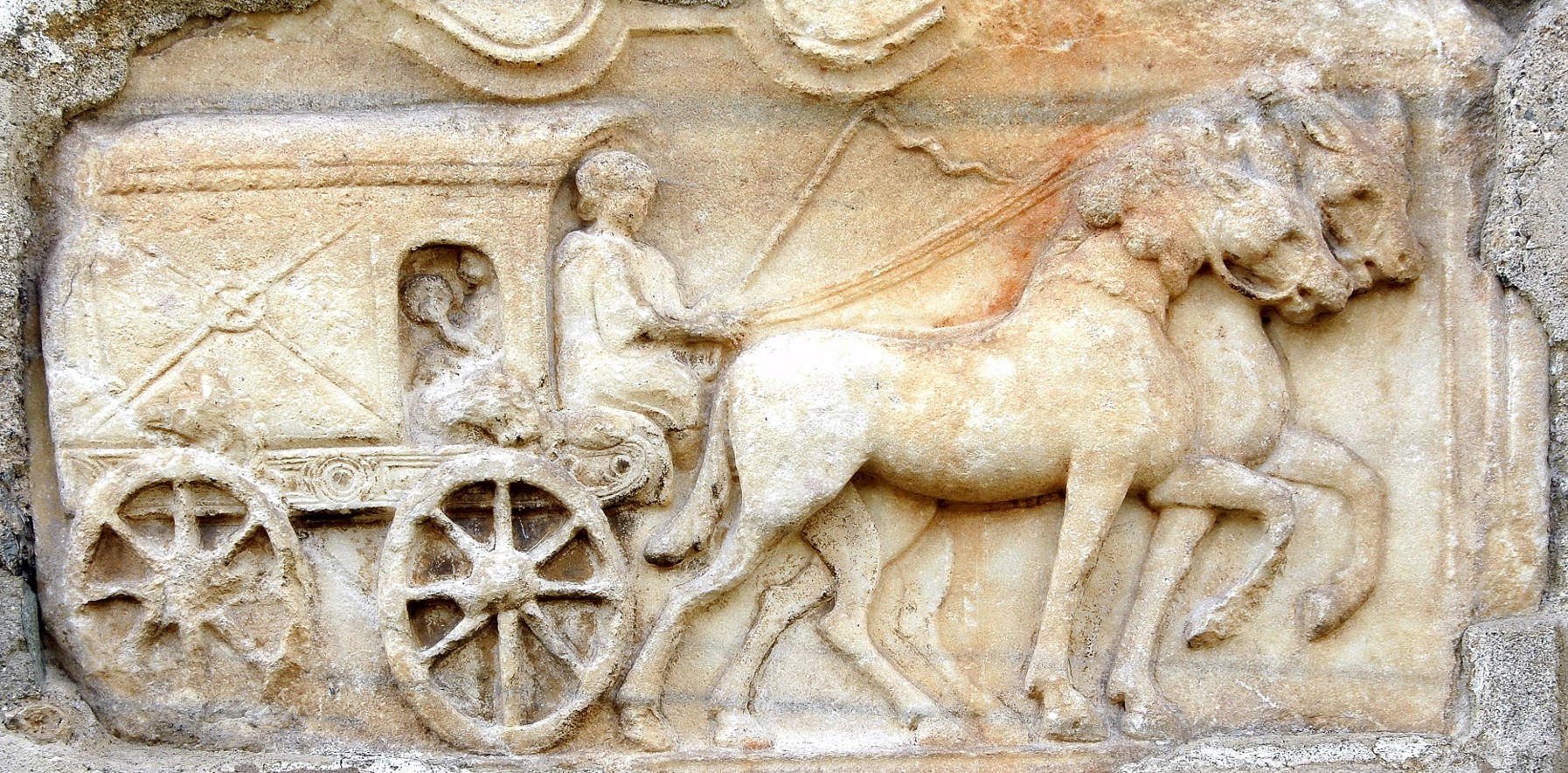
People could travel in different ways, on horseback, in two-horse open carriages or in covered coaches–as in many other areas, the Romans benefited from what the cultures they conquered had to offer and integrated this into their own knowledge: For example, the Romans adopted many Celtic terms, such as carruca for the travelling carriage. The travelling carriages certainly varied greatly in design, depending on the comfort requirements and the person being transported. Travelling was not always a pleasure (heat: Pliny the Younger, Epistulae , 10.15), but it could also offer a pleasant place of ‘seclusion’ (for conversations: Martial, Epigrams , 12.24; for eye ailments: Pliny the Younger, Epistulae , 7.21). Little is known about their appearance. The most important evidence is the relief from Maria Saal in Lower Austria (Figure 27).
Fig. 27: Carruca relief embedded in the wall of the church in Maria Saal, Austria. Photo by J. Jaritz 2023 (license: CC BY-SA 4.0. Available at: https://de.wikipedia.org/wiki/Datei:Maria_Saal_Dom_Grabbaurelief_Reisewagen_in_die_Unterwelt_ 29062007_02.jpg [Accessed 23 Marc 2026].

Such illustrations and finds of cart fragments leave room for interpretation. There have been several replicas, the most famous are from the Romano-Germanic Museum in Cologne (based on the Wardatal finds) and from Colonia Ulpia Traiana in Xanten (Held, 2020, pp.113-133). The Cologne replica has interesting interpretations, but these cannot be verified in the relief or contradict this relief. These include the downwardly narrowing floor, which allows for a wider front axle and thus a smaller turning circle. This, as well as some of the design features (modern tongue-and-groove flooring and coachman's seat), make this reconstruction appear inferior to the one from Xanten when viewed from a scientific perspective (R. Grüßinger, scientific advisor at the Römisch Germanisches Museum Cologne (email 14 April 2025)). The reconstruction of Xanten has been discussed in detail and also tested. However, the construction and thus the equipment are largely determined by the wagon factory in Poland that carried out the work. The iron tyres, wooden rims and wheel diameter are very solid, as is the passenger compartment, which is made entirely of wood. This makes the wagon heavy. Other interpretations have been documented, such as the carriage from the Archaeological Landscape Park in the Eifel municipality of Netterheim, which was destroyed in a fire in 2021 ( https://archaeologischer-landschaftspark.de/erleben/roemischer-reisewagen.html , last access: 12. March 2026).
What all serious replicas have in common is the so-called transverse suspension, which can be seen in the relief (Furger, 2021, pp.19-22). Its effectiveness was tested in Xanten using a vibrating board (Held, 2020, pp.131-133). However, the tests (this also applies to Bodenstein and Bräunling, 2001) provide little insight because the criteria cannot be evaluated by reference to other ancient carriages.
The construction of the FAU was based on the following principles:
a) The setting of parameters for carriage parts to enable the comparability of carriages with different suspension systems, insofar as historical conditions and evidence do not prevent this. These include hubs, axles, wheel diameters of approximately 90 cm, rim dimensions (whereby the Celtic carriage has a rim out of one solid beam and the Roman carriage has a segmented rim (compare the diameter of Xanten)).
b) The lightweight construction of the carriage body, as far as the pictorial and written specifications allow.
The track width was standardised to a certain extent (based on wheel tracks and axle findings), approximately 145 cm (compare the Xanten carriage). The segment wheels were made according to the specified dimensions (diameter 90 cm, rims 5 cm high, 5 cm wide, later shaped conical) by the Wagnermuseum am Kiekenberg near Hamburg. We shrunk the iron tires and hub rings. Two axletrees (ash) were turned to a diameter of 60 mm. Two oak axle bolsters, which rest on the axletrees as support for the reach pole and swing hangers, were made to a length of 1 m, a height of 30 cm and a thickness of 6 cm.
Fig. 28: View on axle bolsters and swing hangers in the background. Photo by B. Dreyer.
Two swing hangers for the rear axle are cut out of solid ash wood with a thickness of 60 mm. It was not possible to bend the rear swing hangers (unlike those on the front axle) due to the tight radii, although swing hangers bent under steam would certainly have provided greater protection against breakage. The swing hangers were fitted into the axle bolsters and secured to the reach pole with iron bolts with a diameter of 10 mm. The reach pole, made of ash wood, serves as a supporting beam between the rear and front axles and is cut to a length of 140 cm, a width of 14 cm and a height of 10 cm. Two swing hangers made of ash wood are bent under steam for the front axle to mount the drawbar. An iron bolt with a diameter of 12 mm is installed in an iron sleeve with an outer diameter of 16 mm and a length of 30 cm as the pivot point and bearing for the front axle. Four ash chassis or frame beams, side stanchions, were fastened with wooden dowels. They are designed to support the passenger cabin suspension. Bronze uprights are inserted at the top. To stabilise the cabin suspension, a 3 mm thick sheet metal plate is bolted on both sides from the upper edge of the respective (two) axle bolsters of the front and rear axles to and over the (respective) side stanchions, which supports the bronze uprights weighing 6.5 kg each (Figure 29). Since the front axle swing hangers has to bear the weight of the drawbar, a crossbar made of ash wood must be constructed on the opposite side of the front axle as a counterweight under the reach pole.
The construction of the passenger cabin begins with the floor panel. It consists of a frame measuring 2.3 m in length, 0.95 cm in width and 8 cm in height. A course correction of 90 degrees should be possible without contact. The initial relief (Figure 27) argues against a higher cabin suspension to prevent contact. The side walls are covered with linen (dyed and painted using the tempera method), the front and rear walls are covered with leather (the covering is attached with several 26 cm long metal strips) and the roof is covered with tanned cowhide leather on curved segments.
Fig. 29: cabin with suspension. Photo by B. Dreyer.
Window openings are also provided on all four sides, three of equal size on the sides and rear wall (approximately 30x40 cm), and another at the front for communication with the coachman (approximately 15x25 cm). They are covered with yarn (fig. 29), between which very thin, translucent and smoothed rawhide (approximately 1 mm) can be inserted. For the ‘transverse suspension’ or free-hanging suspension of the cabin, leather straps lead from the four bronze uprights to the lower cabin frame, where they are attached to hooks. In this way, the cabin frame hangs freely, about 5 cm above the axle frames. This allows the cabin to move a few centimetres in the transverse and longitudinal directions. However, classic vertical spring movement is not possible in this way. The leather straps (approximately 3 mm thick) are three-layered and sewn with hemp thread soaked in beeswax. The lower ring of the leather straps on the front axle is guided in an iron rod and can slide sideways when the axle turns, thus enabling curve driving.
Fig. 30: Carriage body with antique-painted linen on the sides, leather back and front walls, with tanned cowhide leather roof. Photo by B. Dreyer.
Passenger compartment weight` 128 kg, including: chassis without wheels and without drawbar 93 kg, 1 wheel 21 kg, x 4 = 84 kg, 4 windows approximately 1 kg, door linen blind 2.5 kg, 2 linen covers 5.0 kg, strip iron 16 kg, leather front and rear covers, tanned leather roof: 5 kg (Figure 31).
Fig 31: Journey cart ready on the left April 2026, together with the Celtic Chariot. Photo by B. Dreyer.
A find in Croatia from 2021 is set to expand the test spectrum (Figure 32). It is a Roman chariot (with a combined traverse and longitudinal suspension) that will be compared with the capabilities of the Celtic chariot, in the way of providing comfort for person and animals. Results, in cooperation with the Croatian excavators (Hrvoje Vulic) are expected in the end 2026, including the tests. An international and interdisciplinary enterprise of British blacksmiths, German historians and engineers and Croatian archaeologists just started to reconstruct that cart, planned to be ready to participate in the tests in late autumn 2026.
Fig. 32: Excavated Roman luxurious fast cart. Photo by H. Vulic.
Supplying military fortresses and their civilian settlements near the border was a top priority for the Roman provincial administration in the region along the so-called wet and overland limes. However, the most effective supply was by water on the rivers along the border or to the border. The means of transport were barge boats, which, with their shallow draught, could
navigate even the smallest rivers, depending on their meandering course, and in a wide variety of lengths (from 10 to 35 metres, maximum draught of 1 m, maximum width of 6 m) and could carry several tons (between 7 and 80 tons load capacity, compare animals with a maximum load of 135 kg or animals pulling carts with max. 650 kg) to supply entire legions for days, weeks and years. Towed, rowed or poled, assisted by a sail, the barges could travel about 15 km per day upstream and 20 km downstream on a river such as the Lippe.
A legion needed 5 tons per day, 1800 tons per year of grain alone, not including luxury goods and weapons (Jaschke, 2009, pp.197-199). This is documented for the Lippe, for example, by the construction of paths along the riverbank, which ensured that these ships could be pulled.
Fig. 33: Altmühl-river and Roman Limes. Illustration by L. Werther (Dreyer, et al., 2022b, p.39).
This is also likely for the Altmühl-river (Figure 33), which supplied the Roman camps at Gnotzheim and Theilenofen and Gunzenhausen, with a total of around 1,000 men and a requirement of one ton of wheat per day. The Gunzenhausen fort was located at a ford on the Altmühl, which crossed the Raetian Limes to the north-west and thus left the Roman Empire (Dreyer, et al., 2022b, pp.36-38). Barges with a length of about 10 metres would have been able to travel with a load of about 7-8 tons along the meandering Altmühl to the Raetian Limes near Gunzenhausen. According to accounts from the Napoleonic era, from Graben (site of the Fossa Carolina from 798 AD) onwards, the Altmühl had sufficient water flow for ship transport of up to 8 tons. The distance between Graben and Gunzenhausen upstream is 15 km, about a day's journey on the slow-flowing Altmühl.
Our model was the Prahmboot II from Zwammerdam in the Netherlands (Figure 34), which has been replicated several times. Once again, we wanted to stay close to the original using traditional methods, tools, techniques and materials.
Fig. 34: Finding and reconstruction plan of M.D. de Weerd 1988.
a) The new barge, the Alchmona rediviva (medieval rendering of Altmühl), was modelled on De Weerd's plans, on a scale of 1:2. This ensures the required insights (see De Weerd, 2001, p.105) and meets the capacity of a small river like the Altmühl. The joints have all been caulked with hemp thread and then tarred. We have applied a wood preservative varnish up to the assumed waterline. The boat is therefore 11.05 m long (front ramp 2.55 m, rear ramp 1.35 m). It is up to 54 cm high and 165 cm wide at its widest point. It is expected to have a load capacity of around 7 tons.
b) The oak frames, which are alternately aligned to port and starboard, are fastened to the floorboards with bent iron nails (approximately 600 in total in the boat, from the outside to the inside), to fix the floorboards to the L-shaped sides by means of frames at larger intervals (here due to the ‘frame/skeleton first’ construction method), in general therefore according to the ‘shell-first’ principle. After that, the remaining frames were inserted in phases, halving the distances (up to “phase IV” with respect to the phrasing of De Weerd, 2001, p.107). Both knees and forks were attached at the top of the second, clinker-built side plank by a counter-nailed batten, as far as they reached the board, 42 times with respect to the model. Iron cramps stabilised the ramps at the front and rear, as in the prototype; a keel block 5 m long, maximum 9 cm high and 5 cm wide, thickened in the middle to 12 cm for the mast shoe at 80 cm, serves as longitudinal stabilisation in accordance with the prototype.
The launch happened 2025 September 25 th (Figure 35). Tests will be carried out with the boat on the Altmühl to determine its transport and manoeuvring potential (by poling, pulling and sailing).
Fig. 35: Prahm boat after launching. Photo by B. Dreyer.
Case 4: Ancient Painting Techniques and Intended Effect
It is now well established that antiquity was a colourful era, at least as far as the painting of durable materials is concerned (Brinkmann, 2003; Brinkmann and Scholl, 2010). The painting and dyeing of perishable materials have been far less thoroughly researched, but it certainly took place. To this end, the not infrequent but insufficiently utilised statements from written sources, alongside the few material remains, must be made fruitful and empirically reconstructed in terms of causal relationships. This is already yielding important results in the field of ancient encaustic and tempera techniques. In this way, gaps in our understanding can increasingly be filled:
a) Encaustic painting of ancient ships, in which the paint is burned onto the substrate (for example with wax as binder, applied as hot pigment-wax mixture), is only described by Pliny the Elder ( Naturalis Historia , 35.19-20; 35.31; 35.41, apart from a few material exceptions, such as the find in Pisa and Croatia, see above on ships). In many cases, it must be assumed that the natural paint has disappeared before excavations or that no search was made for its residues in the soil. It can be assumed that it was used on all ancient Roman ships, especially military ones, and served a representative, deterrent, but also, in the case of some types of ships, a camouflaging purpose, depending on strategy (Dreyer and Speck, 2021; Carbon, Dreyer and Speck, 2026).
b) The painting of ancient shields has only been handed down in fragments (e.g. Goethert 1996) and by statements of authors such as Pliny the Elder and Vegetius. The most commonly used painting technique was tempera, in which pigments are applied to the substrate using water-soluble binders, usually lean, for example with a high proportion of aqueous and a low proportion of fatty substances. Animal glue was the most common binder, followed to a lesser extent by casein, egg and gum (and in some cases wax), as documented in ancient literature and also confirmed by art-technological examinations of painting residues. Within the EU Interreg-DTP project Living Danube Limes 20 Roman shields from around the third/fourth century AD with the motif–a Victoria with nimbus standing on a globe with a wreath in her right hand and a palm branch in her left–had to be built. A lime-casein tempera technique was used here, which required more layers of paint (primers and motif) and a high pigment content, but was very weather-resistant and easier to handle than animal glue tempera. Based primarily on the finds and the description of Polybios (6.23), we chose the ancient plywood technique for the construction. This means that thin strips of wood were glued together in layers, with the first layer aligned vertically, the second layer horizontally and the third layer again vertically. As in Dura Europos, we chose poplar as the type of wood (not birch as in Fayum attested) and shaped the shield convex and elliptic round (Figure 37).
Fig. 36: Shield template (massive pine) under construction. Photo by B. Dreyer.
On the shape of a solid wood template (Figure 36) the poplar strips were glued together. The glue was a mixture of curd (which contains natural casein) and slaked lime. The adhesive effect of casein and slaked lime was already known in ancient times.
Fig. 37: First layer of poplar strips attached with clamps, the second and third with glue, temporarily fixed with little nails until the layers are dried out for a day. Photo by B. Dreyer.
Either linen (we used a density of about 500 g per square meter) or skin was applied with the same glue to the three layers, which held the shape of the solid wood negative in the dried state (curvature towards the centre 9 cm from the edge). The shield is secured at the edge with cowhide (cattle), which are sewn on and then left to dry.
Fig. 38: The shield gets a hole in the middle, with later reinforced handle, the edge is secured by cowhide, then a primer is applied on both sides. Photo by B. Dreyer.
According to the findings (Nabbefeld, 2008), a hole with a handle (later reinforced) was dug in the centre, with a circular diameter of 12 cm flattened at the bottom. A brass boss with a rim of 4 cm and a curvature of 6 cm was attached to the shield torso with iron nails, which were subsequently cramped.The painting was applied to the shield bodies in layers (Figure 38, 39, 40): First a white layer (lime) was applied to the linen, then a yellow layer (yellow ochre). For the motif, the various pigments were mixed with a self-produced tempera (slaked lime, casein, water). The use of casein as a binding medium was known in antiquity (Pliny the Elder, Naturalis Historia , 36.177). The pigments used (for example various red and yellow ochres, green earth, lime, Egyptian blue, azurite and black from burnt wood) are all verified by ancient sources (Pliny the Elder, Vitruvius or Theophrastus).
Fig. 39: Work in progress: painting of the Victory’s skirt. Photo by B. Dreyer.
Fig. 40: Two of the 20 shields finished. Photo by M. Orgeldinger.
The case of the binding media used for Roman shields remains unsettled, even after scientific analyses on the material remains (for example Gunnison, et al., 2020). Therefore, as various binding media in Roman times are attested by ancient authors, the attempts to reconstruct ancient painting continued, with motifs historically attested (scutum of Dura Europos). This time we tested animal glue as a binding medium (Pliny the Elder, Naturalis Historia , 28.236) in painting and as an adhesive (Pliny the Elder, Naturalis Historia , 7.198). The advantage was that this more easily soluble binder requires smaller amounts of pigment and previous layers of paint could be ‘softened’ and bonded with the (warm) next layer of paint. The disadvantage was that the pigment-binder mixture must always be applied warm (30-40°C). This required practice: After a first white layer with lime, a second layer of a red pigment (different variants) was applied. The motif elements of the scutum from Dura Europos were painted onto this second layer. According to the original an eagle stretching its wings standing on a globe and holding a garland in its beak. It is flanked on both sides by two Victories, each holding a wreath and a palm branch in their hands. In the lower third of the shield there is a lion whose body is painted in side profile, while the head looks out of the shield frontally. The basic colour of the lion is a yellow-brown. The colour is based on the recipe of Vitruvius (7.14.1): coloured water of boiled yellow violets and lime. For the different shades, a small amount of yellow-brown base colour was mixed with green earth and with red ochre and ground carbon black. Marble flour was used for the white highlights (also for the victories and the eagle). The base colour of the eagle and the two Victories is made from yellow ochre and marble flour – except for the flesh tone of the Victories, where ground yellow marble was added to the aforementioned ochre-marble mixture. The shades of the were painted using green earth, red ochre mixed with a little ground carbon black and indigo. The ornaments grouped around the shield boss were painted with the same pigments, except that no pigments were mixed together here–except for the spiral meanders: here yellow ochre was mixed with a little marble flour (Figure 41).
Fig. 41: painted shield with animal glue based on the motive of the scutum from Dura Europos. Photo by Chr. Sponsel-Schaffner.
The use of animal glue has the following advantages over casein for the shields: i) The pigments can be applied over a thinner area. ii) green earth (which could not be painted with thin brushstrokes) as well as lime and marble flour, which were difficult to apply with the lime-casein mixture, could be painted very well in animal glue, which also facilitates (and in some cases enables) finer detailing. iii) Due to the consistency of the animal glue-pigment mixture, it is possible to level out unevenness in the shield body and the covering by applying layers of primer, so that an even painting surface is created even with a wide-textured canvas, for example. iv) Due to the solubility of the animal glue on contact with warm liquid, the different layers of colour can bond with each other, which prevents flaking, especially of primer layers that even out unevenness. v) Despite its general solubility in water, initial tests on painting samples have shown that animal glue is unexpectedly stable in cold water - accordingly, the paint may also have served a general waterproofing purpose on perishable material.
Other tests on alternative attested binding media (mixtures) have to follow to identify the advantages of the respective recipes for the various transient colour carriers.
c) Painting the Roman travelling carriage: The increasing skills in painting perishable materials had profitable cross-effects when painting the linen side coverings of the carriage (see above). The red primer on the linen coverings, on both sides, was applied according to the experience with shields based on the motifs of the scutum from Dura Europos. This also applied to the eagle, using an adapted, in this case lime-casein-tempera technique (with reduced layers of paint, with lower pigment content in the binder mixture, and without the use of oil), because the paint on the linen had to be both flexible and water-resistant without losing depth (shading). It can be said, that different materials require different skills in the range of Tempera-painting (Sponsel-Schaffner, 2024). Effect criteria (recognisability, psychological effect) could be tested empirically. But the painting also has a protective function. The cooperation between ancient history, chemistry, and perception psychology led to new insights regarding the targeted use of colours and painting techniques to achieve the desired effect (such as liveliness), which can also be transferred to other applications.
The field of painted perishable materials is still largely unexplored and yet important - as the example of ships, shields and carriage painting shows: Painting served the purpose of identification and at the same time had to be durable. If the comparatively numerous ancient statements on painting and scientific analyses of the few material records do not allow any clear statements to be made, experimental reconstruction work must be carried out: A difficult but commendable task.
Conclusion
The many promising approaches in empirical archaeology are considered applicable to other disciplines of historical research, especially those sub-disciplines that suffer from a genuine lack of sources, as the examples given show. It is important to ensure that the results can be evaluated beyond the individual case by means of overarching historical questions. It has to be guaranteed the scientific added value by constructing replicas and evaluating them in a historical context (on basis of all material and literal sources and tradition available), in accordance with commonly accepted scientific guidelines.
[MOU1] video
[MOU1] Video type Scorpio
[MOU2] Video type Orsova
[MOU3] Video
[MOU1] Video 3 D Model FAN
[MOU2] Video 3 D Modell Danuvina
[MOU3] Video Building FAN
[MOU4] Videos Building Danuvina and construction and preservation of Danuvina
[MOU5] Video testing on Altmühlsee
[MOU6] Video: testing on Danube